


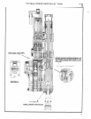
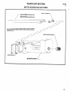
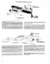

SPINDLE AND LEAD SCREW SECTION
DISASSEMBLY
To remove spindle and sleeve assembly (41242-1) the valve
section must be removed to gain access to bracket (41235) set
screws and taper pin which hold the drive spindle (41239-1) and
shaft (40516-1) together. Remove as outlined under “Valve Sec-
tion”, page 8.
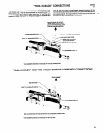
See “Spindle and Lead Screw Section” on page 8 and remove the
valve section and lead screw and nut assembly from the tool.
To remove sensor valve from housing (45443): remove retaining
ring (Y 147-3) and lightly tap housing with a soft face hammer until
bushing (45447) extends enough to grasp with fingers and re-
move with valve stem (39382).
CAUTION: If the tool is mounted in a vertical or near vertical posi-
tion, block the chuck end of the drive spindle to prevent the spindle
from dropping down when set screws and taper pin are removed.
Remove two (2) screws (Y154-53), washers (Y l-l 0) and bracket
(41235). Remove set screws (45445), rotate shaft until “x” identi-
fication mark stamped on o.d. of shaft is up, insert a punch thru
spindle and tap lightly to remove taper pin. After taper pin has
been removed, spindle (41239-1) and shaft (40516-1) may be
separated and spindle assembly removed out thru the front of
housing. Shaft (40516-1) must be removed out thru the rear of
housing,
To remove spindle assembly from housing, carefully slide spindle
assembly from housing, taking care as not to mar sleeve or dam-
age wiper. Remove chuck and arbor with a chuck removal wedge.
Remove nut (40514-1), washer (41259) and spacer (41260) from
drive end of spindle (41239-1). Remove spindle from rear end of
sleeve (41263). NOTE: Bearings (41864) are press fit on spindle.
To remove bearings (41864) remove retaining nut (40515).
Needle bearing (41241) is pressed into sleeve.
To remove driving gear (41366) idler gear (40518) and driven
gear (40517-1), remove five cap screws (Y154-56) and washers
(Y14-10) and carefully pull housings (40507-1 and 40508-2)
apart. Remove gears from housing.
REASSEMBLY
Before reassembling, pack all bearings and lubricate gears liber-
-
ally with 40036-1 grease, or equivalent. NOTE: Whenever a part
containing “0” rings has been removed from the tool, it is recom-
mended that the “0” rings be replaced with new ones before reas-
sembling the part to the tool. Lubricate all “0” rings with “0” ring
.
lube (36460) when assembling.
Press bearings (32325) onto driving gear (41366). Press needle
bearings (31198) into idler gear (40518). Press bearings (31068)
onto driven gear (40517-1).
Place housing (40508-2) in a suitable holding device, with the
gearing end up. Assemble gears (41366 and 40517-1) into hous-
ing (40508-2). Assemble one (1) washer (40512-1) gear assem-
bly (41231) and other washer (40512-1) over dowel pin
(Y148-416). Assemble spindle housing (40507-1) to housing
(40508-2), being careful to maintain alignment of housing with
bearings, gears and dowel pin. Secure housings with cap screws
(Y154-56) and washers (Y14-10).
Assemble spindle (41239-1) into rear end of sleeve (41263) and
press bearings (41864) onto spindle and secure with retaining nut
(40515). Assemble wiper (40503) to sleeve, spacer (41260) and
washer (41259) to spindle, securing with nut (40514-1).
Assemble spindle and sleeve assembly (41242-1) into front of
spindle housing (40507-1), using caution to be sure wiper is in
correct position (see page 9) and that it is not damaged while as-
sembling. Assemble bracket (41235) to sleeve (41263) with
screws (Y154-53) and washers (Y1-10). Assemble chuck and
arbor to spindle.
Assemble lead screw shaft (40516-1) with splined end thru gear
(40517-1) and into spindle (41239-1) aligning holes thru shaft
I
and spindle. Rotate lead screw shaft so the “x” identification mark
stamped on the shaft is down (small end of tapered hole thru shaft
is down and large end of tapered hole is up) and assemble taper
pin (45446) -with long tapered first-thru spindle and lead screw
shaft. Assemble one set screw (45445) into same hole in spindle
against taper pin and tighten set screw, forcing taper pin into lock
position. Torque set screw to 40 in. Ibs (2 in. Ibs.). Rotatespindle
180 degrees and assemble other set screw (45445) into spindle
and torque to 35 in. Ibs. (2 in. Ibs.). When correctly assembled,
no backlash (play) should be evident while holding chuck and end
of lead screw shaft and twisting in opposite directions.
Install valve stem (39382), with “0” ring (Y325-6), into bushing
(45447) with “0” rings (Y325-9) and place in housing (45443) and
secure with retaining ring (Y147-3). For installation of lead screw
and nut assembly, see page 5. Install housing and valve assem-
bly (45452) to housing (40508-2) and secure with washers
(Y14-10) and screws (Y154-53). See “Lube Requirements” on
page 6.
16