


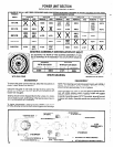
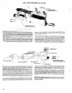
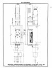
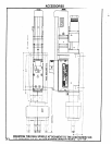

NO-HOLE SENSOR SYSTEM
‘TUBE 44638-010-M
7
PORT
PORT
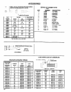
‘THIS NUMBER DENOTES A PACKAGE OF TEN (10).
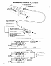
The “B” series Lead Screw Tapper models have a built-in system
that will cause the unit to retract if there is no pre-drilled hole pres-
ent in the workpiece or in an excessive mis-alignment of hole in
workpiece with the tap of tool. To use this system, remove the pipe
plugs in the ports “A”, “D”, “F” and “G”, being sure air supply is dis-
connected from tool before removing pipe plugs. Assemble the fit-
tings supplied with tool (two connectors and two elbows) as
shown above and connect the tubing to fittings as shown (short
tube from port “A” to port “G” and long tube from port “D” to port
7”). To assemble tubes to fittings, simply push tube firmly into fit-
ting - tube will lock in place. To remove tube from fitting, push in on
tube and, at the same time, depress brass sleeve around tube
then pull tube out of fitting.
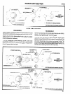
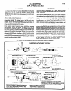
To test reaction and function of no-hole sensor, set the tapper
stroke near maximum. Place a dowel pin in chuck (to represent
tap) and simulate a no-hole condition by using a block of wood or
other suitable object. Start tapper. Upon encountering resistance
to forward movement, the tapper will retract automatically
- so
long as the tap is not engaged in a hole. See below for adjustment.
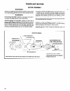
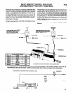
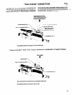
4O502-() LEAD NUT
The “no-hole” sensor valve (39382) located in the rear housing
(45443) is positioned relative to the lead nut (40502). The lead nut
(40502) is spring loaded in the forward position and will activate
the sensor valve when the tap contacts the workpiece in a “no-
hole” or excessive mis-alignment condition. In a “no-hole” or ex-
cessive mis-alignment condition, the lead nut is forced back,
overcoming the spring force against the lead nut and activating
the sensor valve. The sensor valve signals the main retract valve
located in the valve housing for immediate retraction of the unit.
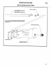
“No- Hole” Sensor Adjustment: The adjustment screw (45444),
which sets the spring tension against the lead nut. is pre-set at the
factory for most applications. If the unit retracts when the tap
45443 HOUSING
makes contact with the pre-drilled hole in the workpiece, rotate
adjustment screw (45444) clockwise to increase spring tension
on the lead nut. The initial setting for the no-hole sensor adjust-
ment is obtained as follows: Turn adjustment screw (45444)
clockwise into housing (45443) until contact is made with spring
(49533). Rotate adjustment screw an additional 1/2 revolution
clockwise (this will produce a .025” to .030” preload on the spring
49533).
NOTE: Four complete revolutions of adjustment screw (45444)
beyond this setting will produce the maximum .250” preload on
the spring (49533).
20