


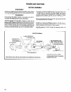

POWER UNIT SECTION
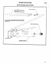
MOTOR ASSEMBLY
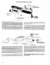
DISASSEMBLY
Remove nut (33694) and sems fastener (33700). Grasp cylinder
in one hand and tap splined end of rotor with a soft face hammer;
motor will come apart.
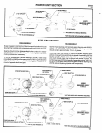
REASSEMBLY
Pack bearings with 40036-1 grease, or equivalent, and coat i.d.
of cylinder with 29665 spindle oil upon assembling.
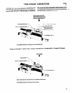
Assemble bearings into end plates, pressing on outer race of
bearings. NOTE: Bearing (33709) is a flush face bearing and must
be assembled with the flush face of bearing towards end plate (let-
tering on bearing facing away from end plate). Assemble end
plate (34485), with spacer (33701), to rotor, pressing on inner race
of bearing. Assemble cylinder over rotor to end plate (34465).
Coat blades (41520) with 29665 spindle oil and assemble to rotor
- straight side out. Assemble end plate (34486), with bearing
(33705), to cylinder and rotor, pressing on inner race of bearing.
Assemble sems fastener (33700) and nut (33694) to motor.
NOTE: Torque fastener to 28 in. Ibs and nut to 9 - 12 ft Ibs.
Be sure rotor does not bind (if motor binds, tap splined end lightly
with a soft face hammer to loosen).
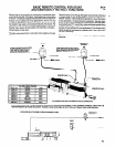
Assemble locating pin (32814) to end plate (34486) and as-
semble motor, with spacers (33699 and 33711), to motor housing,
aligning locating pin with groove in motor housing.
Assemble gearing to motor housing and assemble power unit
section to tool.
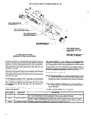
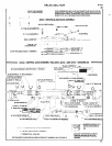
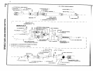
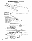
41523 MOTOR ASSEMBLY
q
33709 BEARING (FLUSH
FACE-INSTALL WITH FLUSH
FACE TOWARDS END PLATE)
33699 SPACER
l
34472 CYLINDER
34405 END PLATE
TORQUE TO
9 - 12 FT LBS
41520 BLADES
(5)
INCLUDED WITH 34472 CYLINDER
l
NOT INCLUDED WITH MOTOR ASSEMBLY
PARTS MARKED THUS
q
ARE INCLUDED IN SERVICE KIT NUMBER 45782, SEE PAGE 22.
0 TORQUE TO 28 IN. LBS
14