


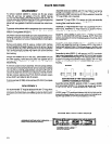

GENERAL DESCRIPTION AND OPERATION
The tapping cycle is started by manually actuating and releasing
“START’ valve at the tool. The start valve must be held long
enough to allow the stop signal valve to close (page 9); about one
(1) second duration for most applications.
NOTE: For very low spindle speeds with medium to fine pitch lead
screw, the signal duration may need to be increased beyond one
second. For very high spindle speeds and short stroke settings,
the signal duration may need to be decreased and positively con-
trolled - consult factory in this case.
The unit will advance the tap to a pre-set depth and automatically
retract to the initial position whereupon the unit will stop with all air
to the unit shut-off. To aid set-up procedure, ‘RETRACT” and
“STOP” may be manually initiated at the tool by actuating one of
two trip tabs located inside the nameplate cover. Swing cover up
for for access (page 4).
WARNING: Do not use fingers to manually actuate trip tabs - use
a blade type screwdriver or similar tool.
The ARO Lead Screw Tapper may be used in a single unit ap-
plication or a multiple unit application.
The maximum stroke length of unit is 2”. Maximum stroke length
of unit with dual spindle head is 1-1/4”.
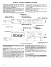
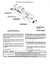
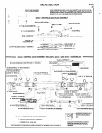
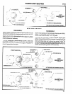
,-ACCESSORY PORT “C”
PORT “D” - CONNECT TO
SENSOR VALVE - PORT “F”-
REMOTE START PORT “B”
SECONDARY EXHAUST EXIT
PORT “F” - SENSOR VALVE
-SENSOR VALVE
REMOTE RETRACT PORT “E”
-PORT “A” -TO SUPPLY AIR TO
SENSOR VALVE - PORT “G”
PRIMARY EXHAUST EXIT
ALL PORTS 1/18” N.P.T.
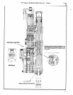
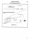
DRIVE GEARING
-MANUAL START VALVE
AUXILIARY GEARING
AIR TUBES
,
ACCESS PORT FOR LEAD NUT
TENSION ADJUSTMENT
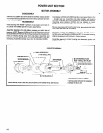
The three basic sections of the Lead Screw Tapper are arranged
for efficient maintenance. The following is a brief description of the
sections and their functions.
VALVE SECTION is composed of a two-way and a four-way
spool valve, both being a two position, double pilot pressure oper-
ated type.
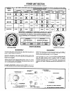
The tap function is manually actuated by the operator while the
“RETRACT” and “STOP” functions are automatically actuated by
the tool. The start valve must be depressed with a short duration of
dwell when starting a cycle from the automatically stopped posi-
tion. Hold valve down only so long as necessary to properly start
the advance (1 second). “RETRACT’ and “STOP” trip tabs need
only be depressed briefly to achieve proper response.
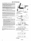
Located between and piloting within the “RETRACT” and “STOP”
valves is actuator (40521-1) with the two trip tabs (40523-1) pilot-
ing on the actuator with set screws provided to hold a positive set-
ting between either trip tab and the actuator (page 4). It is the
purpose of the adjustable trip tabs to provide contact with the
bracket on the traversing spindle drive and properly actuate the
“RETRACT” and “STOP” valves to achieve the proper mode. The
“START” and “RETRACT” functions may be manually operated at
the tool or remotely operated through remote inlet ports using rec-
ommended tubing, fittings and valves (see page 19 for remote
control hook-up).
Each time the “START” valve is depressed, the unit will start in the
advancing (forward) mode.
To start in the retract mode when the unit has been stopped in
mid-stroke, depress and hold retract tab to the left and press the
“START” valve and release retract tab after retraction com-
mences (see warning note above).
2