


MAINTENANCE
Disconnect air supply from the tool or shut off air supply and ex-
haust (drain) line of compressed air BEFORE performing mainte-
nance or service to tool.
Tool maintenance and repair should be performed by authorized,
trained, competent personnel. Maintenance and repair records
should be maintained on all tools. Insure tool is receiving ade-
quate lubrication, as failure to lubricate can create operating
conditions resulting in excessive wear. Insure that the air supply
lines and connectors are of the proper size to provide a sufficient
quantity of air to the tool.
Disassembly should be done on a clean work bench with a clean
cloth spread to prevent the loss of small parts. After disassembly
is completed, all parts should be thoroughly washed in a clean sol-
-
vent, blown dry with air and inspected for wear levels, abuse and
-
contamination. Double sealed or shielded bearings should never
be placed in a solvent unless a good method of relubricating the
bearing is available. Open bearings may be washed but should
not be allowed to spin while being blown dry. When replacement-
parts are necessary, consult the drawing containing the part.
Air tools are made of precision parts and should be handled with
reasonable care when servicing. Excessive pressure exerted by
a holding device may cause distortion of a part. Apply pressure
evenly when disassembling or assembling parts which have a
press fit. When removing or installing bearings, apply pressure to
the bearing race that will be the press fit to the mating part; if this is
not practiced, Brinelling of the bearing races may occur, making
replacement necessary. It is important that the correct tools and
fixtures are used when servicing this air tool.
Before reassembling, lubricate parts where required. Use ARO
33153 grease, or equivalent, in bearings. Use ARO 36460 “0”
ring lube for “0” ring assembly. When assembling “0” rings or
parts adjacent to “0” rings, care must be exercised to prevent
damage to the rubber sealing surfaces. A small amount of grease
will usually hold steel balls and other small parts in place while as-
sembling.
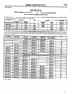
When ordering parts, be sure to list part number, part name,
model number and serial number of tool. Use only genuine
ARO replacement parts.
DISASSEMBLY AND REASSEMBLY OF TOOL
Disconnect air supply from the tool or shut off the air supply and
exhaust (drain) line of compressed air BEFORE performing main-
tenance or service to the tool.
Before starting to disassemble or reassemble this tool (any part or
completely), be sure to read “Maintenance Section”.
To minimize the possibility of parts damage, and for convenience,
the steps for disassembly or reassembly listed on the following
pages are recommended.
Listed below are the three (3) basic sections of the tool and
instructions for removing them.
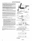
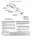
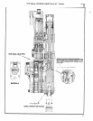
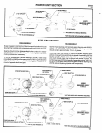
VALVE SECTION
Remove three (3) screws (Y154-53). housing assembly (45452)
spring (49533) and spacer (44848) from the rear of the tool. Place
a suitable wrench on flats of shaft (40516-1) and rotate shaft
clockwise until bracket (41235) has advanced far enough forward
so it no longer contacts stop trip tab (40523-1). If only the valve
section is being removed from the tool at this time, replace spacer
(44848), spring (49533) and housing (45452) and secure with
screws (Y154-53). Remove four (4) screws (Y154-54) and
washers (Y14-10). Lift valve section to clear bracket (41235) and
pull forward carefully to disengage air tubes (41219-). If air tubes
remain with valve section, pull carefully to remove.
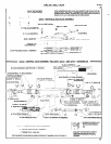
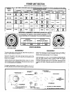
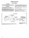
POWER UNIT SECTION
Remove four (4) screws (Y154-55) and washers (Y14-10) and
pull motor and gearing section from housing section. If the unit is
equipped with both drive and auxiliary gearing, remove four (4)
screws (Y154-52) and washers (Y14-10) and pull gearing from
motor section. Grasp end of rotor and pull to remove motor as-
sembly from housing.
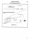
SPINDLE AND LEAD SCREW SECTION
The lead screw and nut assembly (45453-) can be serviced with-
out removing the tool from the fixture mounting. To remove from or
reassemble to tool, see “Lead Screw and Nut” on page 5.
For complete disassembly of a particular section, refer to the ap-
propriate section contained in the following pages.
For additional maintenance information, the manual “Tips on Air Tools”, form 5946 (English) or form 2158-X
(Spanish), is available at $5.00 each, send request
to: The ARO Corporation, One Aro Center, Bryan, Ohio 43506, Attn: “Sales Training”.
8