


GENERAL DESCRIPTION AND OPERATION
32
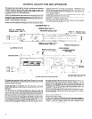
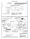
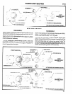
Also contained in the valve section are five (5) 1/8” NPT ports for
PORT “C” is pressurized during the advance and retract cycles
accessory purposes. The ports and their functions are listed as
and is not pressurized when the unit is stopped. This port can be
-
follows:
used to control a valve for coolant, cycle completion, etc. (page
-
21).
PORT “A” - provides constant line pressure. This port is used to
connect air supply to the “no-hole” sensor valve, port “G” (page
PORT “D” is used to connect port “F” of the “no-hole” sensor
20). Do not use this port to supply another unit.
valve to the retract valve in the valve housing (page 20).
_
PORT “B” - use for remote start input (page 19).
PORT “E” - use for remote retract input (page 19).
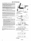
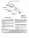
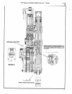
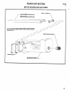
SPINDLE AND LEAD SCREW SECTION has provisions for pri-
mary mounting and houses the spur gear drive train, lead screw
shaft, lead screw assembly, main drive spindle and sleeve and a
“no-hole” sensor valve located in rear housing (45443), see page
20.
The spindle is mounted in a precision sleeve by a pair of ball bear-
ings and a precision roller bearing.
The spindle sleeve is mounted within two precision finished
bronze bushings contained in the spindle housing. The spindle is
connected to the lead screw shaft thru a rigid, no-back-lash cou-
pling. The spindle is free to rotate but axially retained in the sleeve
by the ball bearings. The lead screw shaft is driven thru a sliding
spline connection with a final gear of the three spur gear system.
Feed is accomplished by connecting the lead screw to the rotating
lead screw shaft by means of another rigid, no-back-lash cou-
pling. The lead nut within the lead screw housing has provisions
for tension adjustment with the lead screw. The tension adjust-
ment provision is accessible from the outside of the lead screw
housing by removing pipe plug (Y227-2-L). The lead screw and
nut assembly is easily accessible from the rear of the tool by re-
moving three (3) screws (Y154-53) and housing (45443) and
may be changed to provide another pitch in 10 minutes or less
(see page 5).
The non-interchangeable spur gear system is easily accessible
for maintenance.
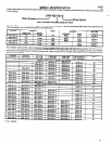
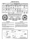
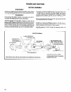
POWER UNIT SECTION is comprised of a reversible motor as- mensurate with the planetary gear reduction of a specific model.
sembly and housing and bolt-on type planetary gearing. The
“2200” series motor develops .60 horsepower at approximately
The planetary gearing is accessible and completely interchange-
half of free speed. The torque and free speed developed is com-
able for easy change of tapping speed. A typical change of
speeds may be accomplished in 15 minutes or less (see page 12).
MOUNTING the unit is accomplished with 5/16”-18 bolts or cap
screws from the underside of the fixture. Keyways are provided in
the units two mounting feet (page 27) and it is recommended that
keys be used for alignment of the unit to the fixture. Keys (45060)
- .500” wide x .375” thick x 1.000” long -are available as optional
equipment.