


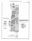

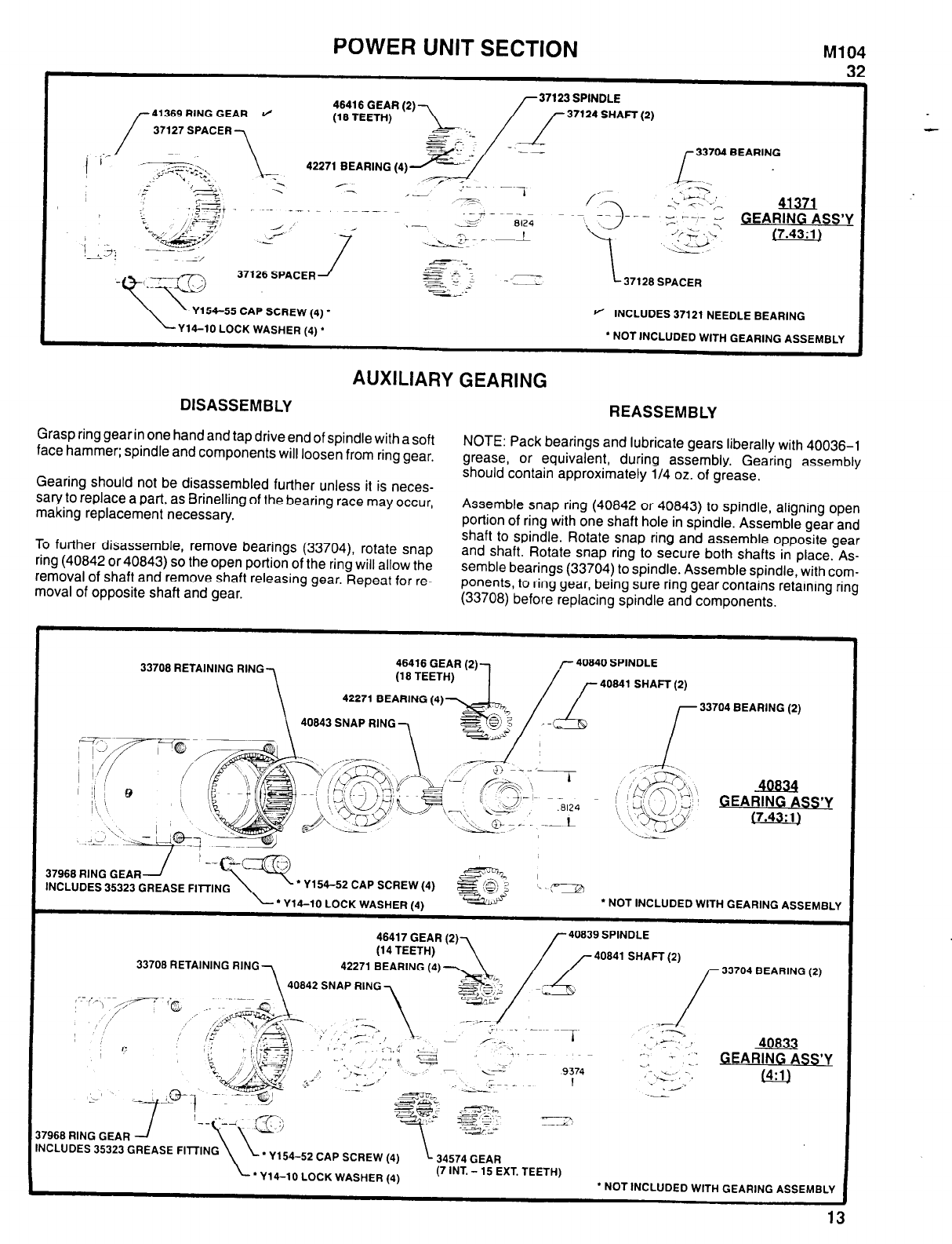
POWER UNIT SECTION
M104
32
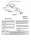
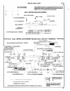
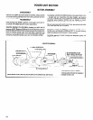
41369 RING GEAR
37127 SPACER
37123 SPINDLE
37124 SHAFT (2)
33704 BEARING
41371
GEARING ASS’Y
(7.43:1)
37126 SPACER
37128 SPACER
--
Y154-55 CAP SCREW (4)
l
Y14-10 LOCK WASHER (4)*
INCLUDES 37121 NEEDLE BEARING
l
NOT INCLUDED WITH GEARING ASSEMBLY
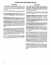
AUXILIARY GEARING
DISASSEMBLY
REASSEMBLY
Grasp ring gear in one hand and tap drive end of spindle with a soft
face hammer; spindle and components will loosen from ring gear.
Gearing should not be disassembled further unless it is neces-
sary to replace a part, as Brinelling of the bearing race may occur,
making replacement necessary.
To further disassemble, remove bearings (33704), rotate snap
ring (40842 or 40843) so the open portion of the ring will allow the
removal of shaft and remove shaft releasing gear. Repeat for re-
moval of opposite shaft and gear.
NOTE: Pack bearings and lubricate gears liberally with 40036-1
grease, or equivalent, during assembly. Gearing assembly
should contain approximately 1/4 oz. of grease.
Assemble snap ring (40842 or 40843) to spindle, aligning open
portion of ring with one shaft hole in spindle. Assemble gear and
shaft to spindle. Rotate snap ring and assemble opposite gear
and shaft. Rotate snap ring to secure both shafts in place. As-
semble bearings (33704) to spindle. Assemble spindle, with com-
ponents, to ring gear, being sure ring gear contains retaining ring
(33708) before replacing spindle and components.
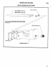
33708 RETAINING RING
40843 SNAP RING
37968 RING GEAR
INCLUDES 35323 GREASE FITTING
l
Y154-52 CAP SCREW (4)
l
Y14-10 LOCK WASHER (4)
l
NOT INCLUDED WITH GEARING ASSEMBLY
33708 RETAINING RING
7968 RING GEAR
INCLUDES 35323 GREASE FITTING
* Y154-52 CAP SCREW (4)
l
Y14-10 LOCK WASHER (4)
(7 INT. - 15 EXT. TEETH)
l
NOT INCLUDED WITH GEARING ASSEMBLY
13