


GENERAL INFORMATION
10
SSR UP6 40, SSR UP6 50PE, SSR UP6 50PEI, HF50–PE, EP50–PE,
HP50–PE, HXP50–PE
http://air.ingersollrand.com
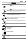
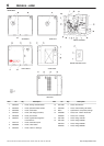
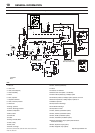
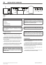
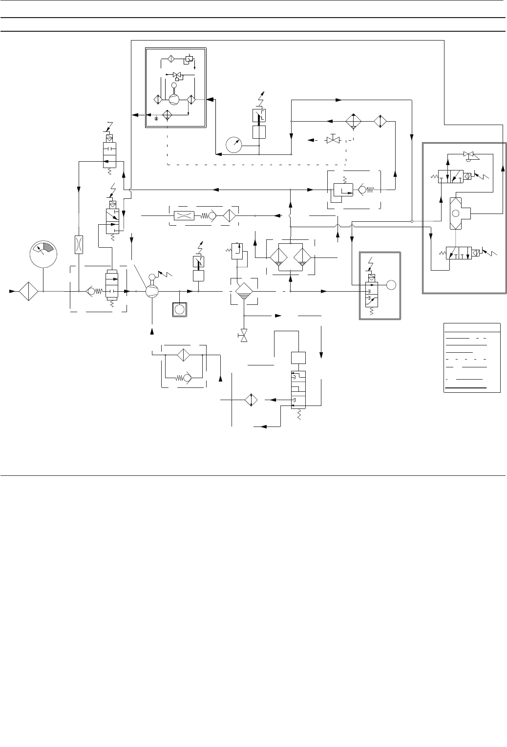
PIPING AND INSTRUMENTATION – Electro–pneumatic and Intellisys Units
KEY
1. Filter, air
2. Valve, inlet
3. Valve, solenoid (load)
4. Airend assembly
5. Motor
6. Tank, separator
7. Separator elements
8. Valve, minimum pressure
9. Aftercooler
10.Gauge, pressure
11.Switch, discharge pressure
12.Switch, temperature
13.Filter, coolant
14.Thermostat
15.Cooler
16 Relay, overload, Motor
17.Valve, safety
18.Valve, drain
19.Screen, scavenge
20 Valve, solenoid (blowdown)
21.Orifice
22 Indicator, air restriction
23.Electric drain valve (EDV – condensate)
24.Valve solenoid (line/sump), Intellisys Option
25.Transducer pressure, Intellisys Option, replaces 10 and 11
26.Sensor temperature, Intellisys Option, replaces 12
27.Moisture separator
28.Compressor air discharge
29.Condensate discharge
30.Compressor air inlet
31.Valve, solenoid, (modulation option)
32.Valve, solenoid, (modulation option)
33.Valve, shuttle, (modulation option)
34.Valve, modulation (modulation option)
35.Sensor, temperature, dryer (option) thermometer or
thermistor–Intellisys
36.Valve, expansion, dryer (option)
37.Filter, refrigerant, dryer (option)
4
1
2
9
18
13
8
10
15
17
19
12
14
16
20
5
11
7
3
21
6
22
PIPING LEGEND
A
B
C
D
E
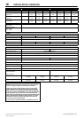
24
25
26
27
23
29
30
INTELLISYS (OPTION)
REPLACES ITEM 12
INTELLISYS (OPTION)
REPLACES ITEMS 10 & 11
F
G
DRYER
OPTION
32
33
31
34
MODULATION (OPTION)
T
M
T
P
28
M
39
35
38
40
41
37
36
27
22292783
Rev F