


39OPERATING INSTRUCTIONS – INTELLISYS OPTION
SSR UP6 40, SSR UP6 50PE, SSR UP6 50PEI, HF50–PE,
EP50–PE, HP50–PE, HXP50–PE
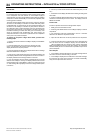
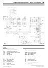
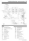
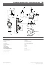
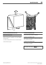
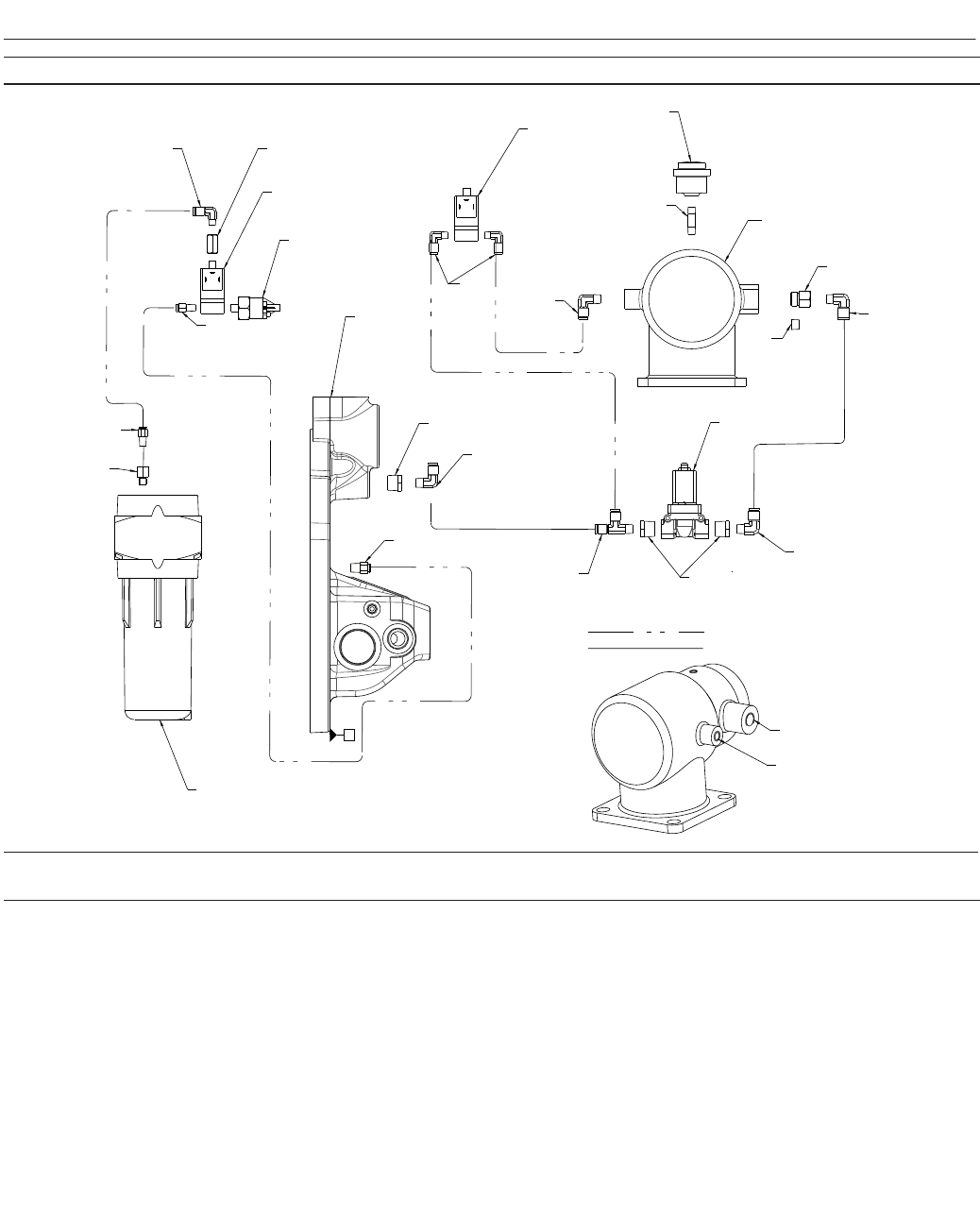
CONTROL PIPING DIAGRAM
KEY
1. Separator tank
2. Pressure transducer
3. Adaptor
4. Connector
5. Moisture separator
6. Elbow
7. Tee, male run
8. Reducer bushing
9. Valve, solenoid (blowdown)
10.Valve, solenoid (load)
11.Indicator air filter
12.Nipple
13.Adaptor
14.Intake valve assembly
15.Line / Sump solenoid valve
16.Tee
17.Valve
18.Plug
NOTES:
A
Tubing 3/8 inch
B
Tubing 1/4 inch
NOTES:
B
A
6 3
2
4
15
1
6
4
7
8
6
9
6
13
14
18
12
11
10
6
6
4
13
5
8
R
P
A
R
P
A
22250047
Revision E
11/04
ADAPTER INTO
THIS PORT
A
http://air.ingersollrand.com