


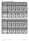
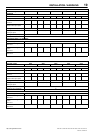

OPERATING INSTRUCTIONS – ELECTRO–PNEUMATIC
25
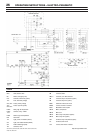
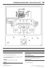
SSR UP6 40, SSR UP6 50PE, SSR UP6 50PEI, HF50–PE,
EP50–PE, HP50–PE, HXP50–PE
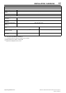
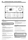
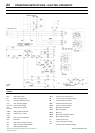
LEGEND
1PS Switch, pressure
1RPS Switch, high refrigerant pressure (option)
2RPS Switch, fan pressure (option)
RST Switch, reset
1SV Valve, solenoid (load) N.C.
3SV Valve, solenoid (blowdown) N.O.
5SV Valve, solenoid (modulation option)
6SV Valve, solenoid (modulation option)
S1 Switch, selector (modulation option)
SS Switch, selector Off/On
TDR1
Relay timed delay (10 sec.)
TDR1a Contact, relay – timed
TDR1b Contact, relay – instant
TR Relay, restart, time delay (6 min)
TRa Contact, relay
VAR Varistor
Barrier terminal strip
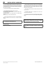
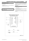
NOTES
1. Approved fused disconnect or circuit breaker per N.E.C.
requirements must be provided by customer.
2. Dashed lines represent wiring by customer.
3. Sizing of electrical components not supplied by Ingersoll Rand is
the responsibility of the customer and should be done in
accordance with the information on the compressor data plate
N.E.C. and local electrical codes.
4.. When changing the supply voltage, ensure that:
a) The motor and the transformer are rewired for the new voltage
b) The motor overload is adjusted to the proper setting.
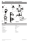
5. Verify actual motor conditions with motor schematic.
http://air.ingersollrand.com