


OPERATING INSTRUCTIONS – INTELLISYS OPTION
38
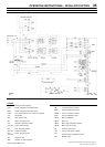
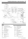
SSR UP6 40, SSR UP6 50PE, SSR UP6 50PEI, HF50–PE,
EP50–PE, HP50–PE, HXP50–PE
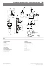
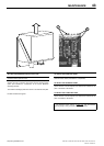
LEGEND
2RPS Switch, fan pressure (option)
RS1 Switch, remote start (option)
RS2 Switch, remote stop (option)
1S
Contactor, star
1Sa, b Contact, aux. star contactor
1SV
Valve, solenoid (load) N.C.
3SV Valve, solenoid (blowdown) N.O.
5SV Valve, solenoid (modulation option)
6SV Valve, solenoid (modulation option)
10SV Valve, solenoid (line/sump)
Barrier terminal strip
BLK Black
BLU Blue
GRN Green
RED Red
WHI White
NOTES
1. Approved fused disconnect or circuit breaker per N.E.C.
requirements must be provided by customer.
2. Dashed lines represent wiring by customer.
3. Sizing of electrical components not supplied by Ingersoll Rand is
the responsibility of the customer and should be done in
accordance with the information on the compressor data plate
N.E.C. and local electrical codes.
4.. When changing the supply voltage, ensure that:
a) The motor and the transformer are rewired for the new voltage
b) The motor overload is adjusted to the proper setting.
5. Blue wire – 16volts A.C.
6. Verify actual motor connections with motor schematic.
http://air.ingersollrand.com