


INSTALLATION / HANDLING
13
SSR UP6 40, SSR UP6 50PE, SSR UP6 50PEI, HF50–PE, EP50–PE,
HP50–PE, HXP50–PE
http://air.ingersollrand.com
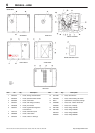
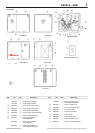
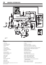
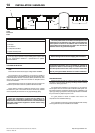
KEY
A Pre filter
B Compressor and cooling air intake
C Starter box
D Cooling air exhaust
E 1.5” NPT air discharge
F Customer power inlet
G Fork lift openings
(Fork lift hole covers must be installed after unit is in place to
reduce noise and ensure proper cooling of package)
H .25 Inch female NPT moisture separator drain.
J Emergency stop button
K Primary compressor service door
L 4 holes, 0.67 Inch (17mm) diameter
M 4 holes, 0.47 Inch (12mm) diameter
N Dryer cooling air intake
NOTES
1. Coolant (lubricant) fill quantity (approximate) 5.5 US gallons
(21 litres).
2. Recommended clearance in front of control panel door 42 inches
(1067 mm) or minimum as required by the latest national electrical
codes (NEC) or applicable local codes.
3. Recommended clearances on left and right sides 36 inches
(914mm).
4. Minimum recommended clearance for the rear of the compressor
is to be 6 inches (152mm).
5. External piping shall not exert any unresolved moments or forces
on the unit. Use pipe size as large or larger at discharge connection.
6. There should be no plastic or pvc piping attached to this unit or used
for any lines downstream.
7. Any field installed ducting to and from the compressor cannot add
more than 1/2 inch (12.5mm) water gauge total air resistance.
Ducting is not recommended for the dryer cooling air inlet and outlet
openings.
8. Do not pipe into a common header with a reciprocating compressor,
unless the reciprocating compressor utilizes a discharge pulsation
damper.
9. Sizing of electrical components not supplied by Ingersoll Rand is
the responsibility of the customer and should be done in accordance
with the information on the compressor data plate and national and
local electrical codes.
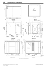
NOTE
All dimensions are in millimetres (inches) unless otherwise stated.
Ensure that the correct fork lift truck slots or marked lifting points are
used whenever the machine is lifted or transported.
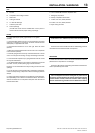
UNPACKING
The compressor will normally be delivered with a polythene cover.
If a knife has to be used to remove this cover ensure that the exterior
paintwork of the compressor is not damaged.
Ensure that all transport and packing materials are discarded in a
manner prescribed by local codes.
NOTE
Units are shipped with transit locking bolt in place. Prior to
running the unit the shipping bolt must be removed and the belt
tension checked. Loosen, remove and discard 10mm shipping
bolt. For belt tensioning procedure refer to Maintenance section.