


MAINTENANCE
46
SSR UP6 40, SSR UP6 50PE, SSR UP6 50PEI, HF50–PE, EP50–PE,
HP50–PE, HXP50–PE
MODULATE CONTROL VALVE ADJUSTMENT
Ensure that the compressor is isolated from the compressed air system
by closing the isolation valve and venting pressure from the drip leg.
Ensure that the main power disconnect switch is locked open and
tagged.
1. Put the compressor in the MODULATION mode by placing control
selector switch SS in the “MODULATION” position. (Non–(Intellisys
models).
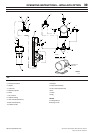
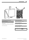
2. Remove 1/4” plastic plug from the tee (18) in the regulator valve.
Connect a pressure gauge to this port.
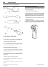
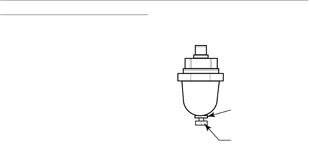
3. Loosen the adjustment screw locknut and back out adjusting screw
3 turns. See Figure 2
4. Put the main power disconnect switch in the ON position.
5. Open the isolation valve and start the compressor.
6. Adjust the isolation valve to bring the discharge air pressure to the
rated discharge pressure (100, 125, 140, or 200 psig).
7. While maintaining the rated discharge pressure, turn the adjustment
screw on the modulation valve (see Figure 2) so that the test pressure
gauge reads:
30 psig for modulate 60% cfm.
Tighten the adjustment screw locknut.
8. Press UNLOADED STOP. Wait for sump pressure to go 0 psig.
Close the isolation valve or vent off all system air.
9. Put the compressor in the desired control mode.
10.Remove the test pressure gauge and replace 1/4” plastic plug.
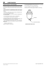
ADJUSTING SCREW
LOCKNUT
FIGURE 2 MODULATION VALVE
http://air.ingersollrand.com