


!&''"!
%J)%
'%!#('"!!'"!&
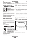
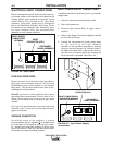
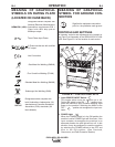
Before installing the machine check that the input sup-
ply voltage, phase, and frequency are the same as the
voltage, phase, and frequency as specified on the
welder Rating Plate located on the Case Back
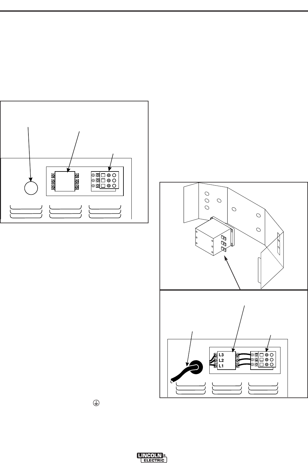
Assembly. Input power supply entry is through the
hole in the Case Back Assembly. See Figure A.2 for
the location of the machine’s input cable entry open-
ing, Input Contactor (CR1), and reconnect panel
assembly for dual voltage machines.
(%%2.?#.;29
(&!*%&-&
Protect the input circuit with the super lag fuses or
delay type circuit breakers listed on the Technical
Specifications page of this manual for the machine
being used. They are also called inverse time or ther-
mal/magnetic circuit breakers.
"!"' use fuses or circuit breakers with a lower
amp rating than recommended. This can result in “nui-
sance” tripping caused by inrush current even when
machine is not being used for welding at high output
currents.
Use input and grounding wire sizes that meet local
electrical codes or see the Technical Specifications
page in this manual.
%"(!"!!'"!
Ground the frame of the machine. A ground
terminal marked with the symbol ( ) is located inside
the Case Back of the machine near the input contac-
tor. Access to the Input Box Assembly is at the upper
rear of the machine. See your local and national elec-
trical codes for proper grounding methods.
!#('#"*%&(##,"!!'"!&
A qualified electrician should connect the input power
supply leads.
1. Follow all national and local electrical codes.
2. Use a three-phase line.
3. Remove Input Access Door at upper rear of
machine.
4. Follow Input Supply Connection Diagram located
on the inside of the door.
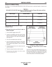
5. Connect the three-phase AC power supply leads
L1, L2, and L3 to the input contactor
terminals in the Input Box Assembly by passing
them thru the three aligned .50” diameter holes in
the baffle and tighten them in the terminal connec-
tors. Be sure to close the baffle by inserting the
tab into the slot in the baffle. See Figure A.3.
(%;=BA#<D2?&B==9F
<;;20A6<;@
INPUT SUPPLY
CABLE ENTRY
OPENING
INPUT
CONTACTOR (CR1)
RECONNECT
PANEL ASSEMBLY
INPUT SUPPLY
CABLE ENTRY
OPENING
INPUT
CONTACTOR (CR1)
RECONNECT
PANEL ASSEMBLY
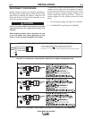
INPUT POWER SUPPLY
CABLE WITH BUSHING
OR BOX CONNECTOR
INPUT
CONTACTOR (CR1)
RECONNECT
PANEL ASSEMBLY
INPUT POWER SUPPLY
CABLE WITH BUSHING
OR BOX CONNECTOR
INPUT
CONTACTOR (CR1)
RECONNECT
PANEL ASSEMBLY