


"#%'"!
%J)%
%&'%!*'%J)%!
'!&'%'"%
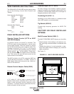
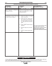
When electrical strikeouts exceed 1 3/4” (44.4mm) an
NA-3 Start Board may be required to improve arc strik-
ing.
When the NA-3 Start Board is used to improve arc strik-
ing, use the following procedures:
1. Set start time at 0.
2. Set NA-3 start current and start voltage at mid-
range.
3. Set the NA-3 output current and voltage to the prop-
er settings for the welding procedure to be used.
4. Turn the Start Board Timer to maximum.
5. Set Start Board current and voltage control.
• Set the Start Board current control to 1 1/2 dial num-
bers below that set on the NA-3 current control.
• Set the Start Board voltage control equal with the
NA-3 voltage control setting.
!"' These Start Board current and voltage set-
tings result in a start up current that is lower than
the NA-3 current setting and approximately equal
with the NA-3 voltage setting for the desired weld-
ing procedure.
6. Establish the correct arc striking procedure with
the NA-3 Start Board timer set at maximum.
• For the best starting performance, the NA-3 Open
Circuit Voltage Control and Voltage Control set-
ting should be the same. Set the Inch Speed
Control for the slowest inch speed possible.
• To adjust the Open Circuit Voltage Control to get
the best starting performance, make repeated
starts observing the NA-3 voltmeter.
When the voltmeter pointer swings smoothly up to
the desired arc voltage, without undershooting or
overshooting the desired arc voltage, the Open
Circuit Voltage Control is set properly.
If the voltmeter pointer overshoots the desired
voltage and then returns back to the desired volt-
age, the Open Circuit Voltage Control is set too
high. This can result in a bad start where the wire
tends to "Blast off."
If the voltmeter pointer hesitates before coming
up to the desired voltage, the Open Circuit
Voltage Control is set too low. This can cause the
electrode to stub.
• Set NA-3 Start Board current and voltage as
close to the welding procedure current and volt-
age as possible.
NOTE: The Start Board current and voltage
should be as close as possible to the welding pro-
cedure current and voltage, while still getting sat-
isfactory starts.
• Set the start time to as low a time as possible
while still getting satisfactory starts.
7. Start and make the weld.
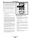
%J )% #"*%
&"(%&''! *!"!!'
'"!*%%
When using the IDEALARC® DC-600 VRD with the
NA-5 wire feeder, set the controls on the IDEALARC®
DC-600 VRD as follows for the best performance:
1. Turn OFF main AC input power supply to the IDE-
ALARC® DC-600 VRD.
2. Connect the electrode cables to terminal polarity
to be used.
3. Connect the #21 work lead (on T.S.2) to the
same polarity as the work cable connection.
4. Set the IDEALARC® DC-600 VRD
LOCAL/REMOTE Switch to REMOTE.
5. Set the IDEALARC® DC-600 VRD OUTPUT
TERMINALS switch to REMOTE.
6. Set the IDEALARC® DC-600 VRD WELDING
MODE SWITCH to the position that matches the
welding process being used.
• For submerged arc welding, set WELDING
MODE SWITCH to CV SUBMERGED ARC posi-
tion.
• For all open arc welding processes set WELDING
MODE SWITCH to CV INNERSHIELD position.