


C6
C6
'""!'!'&
Page
;@A.99.A6<; &20A6<;
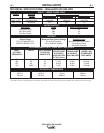
Technical Specifications ............................................................................................. A-1
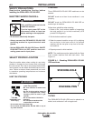
Safety Precautions ..................................................................................................... A-2
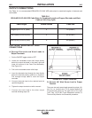
Select Proper Location.................................................................................................A-2
Limit on Stacking ...................................................................................................A-2
Stacking.................................................................................................................A-2
Tilting .....................................................................................................................A-2
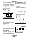
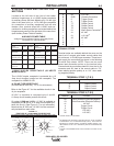
Electrical Input Connections ....................................................................................... A-3
Fuses and Wire Sizes............................................................................................A-3
Ground Connection .............................................................................................. A-3
Input Power Supply Connections...........................................................................A-3
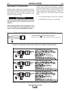
Reconnect Procedure ................................................................................................ A-4
Output Connections ................................................................................................... A-5
Electrode, Work and #21 Lead ..............................................................................A-5
Auxiliary Power and Control Connections .............................................................A-6
________________________________________________________________________
"=2?.A6<; &20A6<;
Safety Precautions ............................................................................................... B-1
General Description ............................................................................................. B-2
Recommended Processes and Equipment ...........................................................B-2
Design Features and Advantages ........................................................................B-2
Welding Capability ............................................................................................... B-3
Meaning of Graphical Symbols on Case Front......................................................B-3
Meaning of Graphical Symbols on Rating Plate ....................................................B-4
Meaning of Graphical Symbol for Ground Connection ..........................................B-4
Controls and Settings ....................................................................................B-4, B-5
Auxiliary Power in MS - Receptacle.......................................................................B-5
Overload, Overcurrent and Fault Protection..........................................................B-6
VRD Voltage Reduction Device Operation............................................................B-6
Operating Steps ................................................................................................... B-7
Remote Control of Machine Operation ..................................................................B-7
Welding Procedure Recommendations ............................................................... B-7
Semi-Automatic and Automatic Wire Feeding
with a IDEALARC® DC-600 VRD and Wire Feeders............................................B-7
NA-3 Automatic Wire Feeder ..........................................................................B-8
NA-5 Automatic Wire Feeder ..........................................................................B-9
________________________________________________________________________
002@@<?62@&20A6<;
Wire Feeders and Tractors....................................................................................C-1
Field Installed Options...........................................................................................C-1
Remote Output Control (K775 or K857)..........................................................C-1
Remote Control Adapter Cable (K864)...........................................................C-1
Undercarriages (K817P, K842).......................................................................C-1
Paralleling Kit (K1611-1).................................................................................C-1
TIG Module (K930-2) ......................................................................................C-1
Factory or Field Installed Options..........................................................................C-1
Multi-Process Switch (K804-1)........................................................................C-1
Connections for Semi-Automatic or Automatic Wire Feeder Control ....................C-3
________________________________________________________________________