


(%%20<;;20A#.;29<.?1#<@6A6<;@3<?&6;492)<9A.42 .056;2@
L3
L2
L1
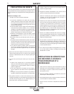
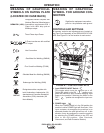
LINES
INPUT
GND
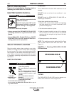
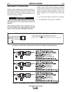
SEE MACHINE RATING PLATE FOR REQUIRED INPUT SUPPLY VOLTAGE
1
.TURN OFF THE INPUT POWER USING THE DISCONNECT SWITCH AT THE FUSE BOX
2.CONNECT TERMINAL MARKED TO GROUND PER NATIONAL ELECTRIC CODES.
3
.CONNECT THE L1, L2, & L3 INPUT SUPPLY LINES TO INPUT SIDE OF THE CRI CONTACTOR AS SHOWN.
W
V
U
CONTACTOR
CRI
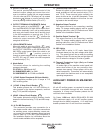
L3
L2
L1
LINES
INPUT
GND
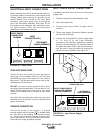
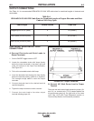
SEE MACHINE RATING PLATE FOR REQUIRED INPUT SUPPLY VOLTAGE
1
. TURN OFF THE INPUT POWER USING THE DISCONNECT SWITCH AT THE FUSE BOX
2. CONNECT TERMINAL MARKED TO GROUND PER NATIONAL ELECTRIC CODES.
3
. CONNECT THE L1, L2, & L3 INPUT SUPPLY LINES TO INPUT SIDE OF THE CRI CONTACTOR AS SHOWN.
W
V
U
CONTACTOR
CRI
(%%20<;;20A#.;29<.?1#<@6A6<;@3<?)N .056;2@
!&''"!
%J)%
%"!!'#%"(%
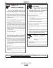
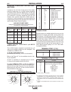
Multiple voltage machines are shipped connected to
the highest input voltage listed on the machine’s rating
plate. Before installing the machine, check that the
Reconnect Panel in the Input Box Assembly is con-
nected for the proper voltage.
.69B?2A<3<99<DA52@26;@A?B0A6<;@0.;0.B@2
6::216.A23.69B?2<30<:=<;2;A@D6A56;A52
:.056;2
*52;=<D2?6;4D2912?3?<:.42;2?.A<?/2@B?2
A<AB?;<33D2912?36?@A/23<?242;2?.A<?6@@5BA
1<D;6;<?12?A<=?2C2;A1.:.42A<A52D2912?
------------------------------------------------------------------------
To reconnect a multiple voltage machine to a different
voltage, remove input power and change the position
of the reconnect board on the Reconnect Panel.
Follow The Input Connection Diagram located on the
inside of Case Back Input Access Door. These con-
nection diagrams for the following codes are listed
below.
1. For 415 Single Voltage, see Figure A.4. (S17894)
2. For 230/460/575, see Figure A.5. (M15666)
('"!