


!&''"!
%J)%
"('#('"!!'"!&
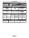
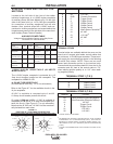
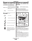
See Table A.1 for recommended IDEALARC® DC-600 VRD cable sizes for combined lengths of electrode and
work cables.
'
%J)%./92&6G2@3<?<:/6;212;4A5@<3<==2?920A?<12.;1*<?8
./92.ABAFF092
./92&6G2#.?.9929./92@./922;4A5
1/0 (53mm
2
)2
2
2
Lengths up to 150 ft. (46m)
2/0 (67mm
2
)150 ft.(46m) to 200 ft (61m)
3/0 (85mm
2
)200 ft.(61m) to 250 ft.(76m)
'%"*"%!
"!!'"!&
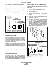
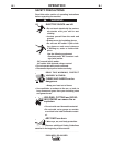
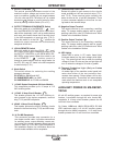
<;;20A920A?<12 .;1*<?82.1@ A<
"BA=BA'2?:6;.9@
1. Set the ON/OFF toggle switch to OFF.
2. Locate the retractable strain relief loops directly
below the output terminals in the lower right and
lower left corners of the Case Front Assembly.
See Figure A.6.
3. Pull out the retractable strain relief loops.
4. Insert the electrode lead through the loop directly
below the desired polarity (positive or negative).
Pull through enough cable to reach the output
terminals.
5. Connect electrode lead to the desired terminal
(positive/negative).
6. Tighten the output terminal nut with a wrench.
7. Connect the work lead to the other output
terminal following steps 4-6.
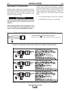
(%"BA=BA'2?:6;.9@
<;;20A *<?8 &2;@22.1A< #?<=2?
'2?:6;.9
There are two work sense lead connection points (+21
and -21) on terminal strip (T.S.2) located behind the
hinged access panel on the right side of the case
front. See 14 Pin MS Type Receptacle section or
Terminal Strip Section for connection procedure.