


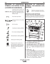
'% !&'%#&
Terminal strips are available behind the cover on the
case front to connect wire feeder control cables that
do not have a 14 Pin MS-type connector. These termi-
nals supply the connections as shown in the following
Terminal Strip charts. NOTE: There are two work
sense lead connection points on the terminal strip.
Connect both the work sense lead #21 from the 14 pin
connector and #21 lead of the control cable to “-21”
when welding positive polarity or to “+21” when weld-
ing negative polarity.
'% !&'%#'&
'% !&'%#'&
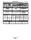
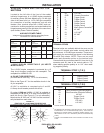
Lead No. Function
75 Output Control
76 Output Control
77 Output Control
Lead No. Function
+21
Work Connection (Electrode Negative)
-21
Work Connection (Electrode Positive)
41 42 VAC
4 Trigger Circuit
2 Trigger Circuit
31 115 VAC
32 115 VAC
(1)
!&''"!
%J)%
(+%,#"*%!"!'%""!
!'"!&
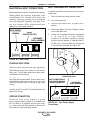
Located at the left side of the front of the welder
behind a hinged cover is a 115VAC duplex receptacle
for auxiliary power (60 Hertz Models only). On the right
side of the case front is a 14 Pin MS type receptacle
for connection of auxiliary equipment such as wire
feeders. Also, terminal strips with 115VAC and con-
nections for auxiliary equipment are located behind the
hinged access panel on the right side of the case front.
(see Auxiliary Power Table for details)
) (#+ %#' %'-
"&"!,
The 115VAC duplex receptacle is protected by a 15
Amp circuit breaker located on the nameplate. The
receptacle is a NEMA 5-15R.
(+%,#"*%'
Voltage and Circuit Breaker Ratings at Auxiliary Power
Connections for Various Models
Auxiliary 60 Hz 50/60 Hz
Power Models Models
Connections
At Duplex 15A No Duplex
Receptacle 115V
Terminal strip 115V 15A 115V 15A
terminals 31 & 32
MS-Receptacle 115V 15A 115V 15A
pins A & J
MS-Receptacle 42V 10A 42V 10A
pins I & K
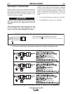
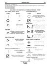
#! N!" (!'"!
A 32 115 VAC
B GND Chassis Connection
C2 Trigger Circuit
D4 Trigger Circuit
E 77 Output Control
F 76 Output Control
G 75 Output Control
H 21 Work Sense
Connection
I 41 42 VAC
J 31 115 VAC
K 42 42 VAC
L --- ---
M --- ---
N --- ---
F=76
G=75
H=21
I=41
J=31
K=42
A=32
B=GND
C=2
D=4
E=77
L
N
M
F=76
G=75
H=21
I=41
J=31
K=42
A=32
B=GND
C=2
D=4
E=77
L
N
M
F=76
G=75
H=21
I=41
K=42
B=GND
C=2
D=4
E=77
L
N
M
F=76
G=75
H=21
I=41
K=42
B=GND
C=2
D=4
E=77
L
N
M
115VAC circuit is on all models.
As shipped from the factory Lead #21 from the 14 Pin connector
is connected to “-21” on the terminal strip (T.S.2). This is the con-
figuration for positive welding. If welding negative polarity, con-
nect lead #21 to the “+21” connection point on the terminal strip
(T.S.2).
115VAC is not available at the 14 Pin connector on Codes 11707,
11725.
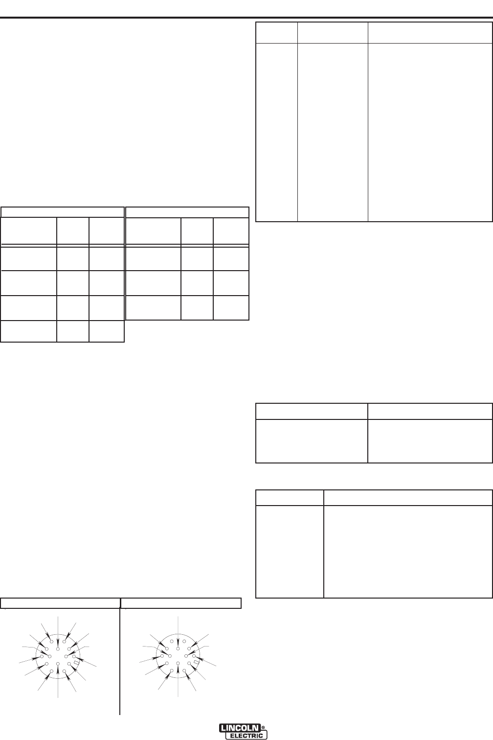
N#! &',#%#'
(For MS3106A-20-27PX Plug. L.E.C. Part #S12020-32)
Refer to the Figure A.7 for the available circuits in the
14 pin receptacle.
42 VAC is available at receptacle pins and .
A 10 amp circuit breaker protects this circuit.
On codes .;1115 VAC is available at
receptacle pins and . A 15 amp circuit breaker pro-
tects this circuit. (See Figure A.7 for pin allocation).
Note that the 42 VAC and 115 VAC circuits are electri-
cally isolated from each other.
%"!')*"#!"!!'"%%#'
'./923<?<12@
Auxiliary 60 Hz 50/60 Hz
Power Models Models
Connections
At Duplex 15A No Duplex
Receptacle 115V
Terminal strip 115V 15A 115V 15A
terminals 31 & 32
MS-Receptacle 42V 10A 42V 10A
pins I & K
'./923<?<12@
(%
#6;9<0.A6<;3<?<12@
#6;9<0.A6<;3<?<12@