


'%"(&""'!
%J)%
If for any reason you do not understand the test procedures or are unable to perform the tests/repairs safely, contact your
<0.96;0<9;BA5<?6G216291&2?C602.0696AF for technical troubleshooting assistance before you proceed.
('"!
If all recommended possible areas
of possible cause have been
checked and the problem persists,
<;A.0AF<B?9<0.96;0<9;
BA5<?6G216291&2?C602.0696AF
#%" &
&, #'" &
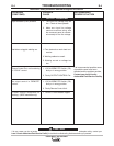
Machine has minimum output and
no control.
The machine does not have maxi-
mum weld output.
#"&&
(&
1. If a remote control unit is NOT
connected to the terminal strip
#75, #76, and #77 terminals, or is
not connected to the 14 pin MS
receptacle the LOCAL/REMOTE
SWITCH must be in the "Local"
position.
2. If a remote control cable is con-
nected to terminals #75, #76 and
#77 or is connected to the 14 pin
MS receptacle the leads may be
"shorted" to the positive weld out-
put.
3. Make certain the Three Phase
input voltage is correct and
matches the machine rating and
the reconnect panel.
1. Check all Three-Phase input
lines at the DC600. Make sure
input voltages match machine
rating and reconnect panel.
2. Put LOCAL/REMOTE SWITCH
(SW3) in "LOCAL" position. If
problem is solved then check
remote control unit or wire
feeder.
3. Check for loose welding cable
connections.
%" !
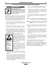
"(%&"'"!
"('#('#%" &
"/@2?C2.99&.32AFB61296;2@12A.6921A5?<B45<BAA56@:.;B.9