


'%"(&""'!
%J)%
Observe all Safety Guidelines detailed throughout this manual
If for any reason you do not understand the test procedures or are unable to perform the tests/repairs safely, contact your
<0.96;0<9;BA5<?6G216291&2?C602.0696AF for technical troubleshooting assistance before you proceed.
('"!
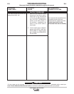
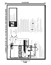
!#"*%"!"&*'&
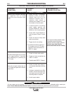
1. Turn off the machine input power (" < "position).
SW1 has 115 volts across it when the input power
is connected.
2. Isolate the switch to be tested by removing all co-
nnecting leads.
3. Check to make sure the switch is making open and
closed connections with a V.O.M. meter. Put ohm
meter on X1 scale. The meter should read zero
resistance with switch "
I " and infinite with switch
"
< "
4. Put the ohmmeter on X1K scale and measure the
resistance between the terminal and the case of the
machine (touch a self-tapping screw). Reading
should be infinite.
5. If either step (3) or step (4) fails, replace the switch.
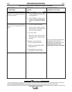
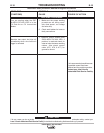
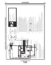
! "('#(' "!'%"%"
&''"! !%
1. Turn machine off (" <" position).
2. Remove the screws from the hinged control panel
and open the panel.
3. Turn the LOCAL/REMOTE CONTROL switch to
"REMOTE".
4. With an ohmmeter on X1K, connect it to lead 236
and 237 on R1.
5. Exercise caution to avoid damaging rheostat tabs.
6. Rotate the OUTPUT voltage control rheostat. The
resistance reading should be from around zero to
10K ohms. Check the resistance reading between
the two outer tabs on the rheostat (leads 236 and
75). The reading must be 10K "10% ohms. No
reading will indicate an open rheostat and a low
reading will indicate a shorted or partially shorted
rheostat; in either case, replace.
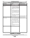
"!!'!% "'"('#('
"!'%"%"&'''"' !
Extreme caution must be observed when installing or
extending the wiring of a remote control. Improper
connection of this unit can lead to loss of control
and/or poor welding. Only the green lead can and
should be grounded to the machine case. When
extending the standard remote control, make sure the
leads are the same and the splice is waterproof. Be
very careful not to ground the cable when in use and
don't let the lugs touch against the case.
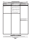
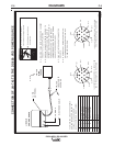
! % "' "('#(' "!'%"
%"&''
Disconnect the remote output control and connect an
ohmmeter across 75 and 76 and rotate the rheostat in
the remote control. The resistance reading should go
from zero to 10K ohms. Repeat with ohmmeter across
77 and 76 with same results. Connect ohmmeter
across 75 and 77. The reading should be 10K "10%
ohms. A lower reading will indicate a shorted or par-
tially shorted rheostat. A very high reading will indicate
an open rheostat. In either of the last two cases,
replace rheostat. Check cable for any physical dam-
age.
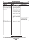
#"%'%"(&""'!(
)%#"%
1. LED’s 4 and 5 indicate power being supplied to the
P.C. board from the 42 volt winding on the main
transformer (T1), but only when the machine is in
CC mode. If LED 4 and 5 are not “ON” while in CC
mode, turn the machine off, check the wiring back
to the 42V transformer winding and check the mode
switch. If the LED’s are on when the machine is in
CV mode then a wiring error exists. <?<12@
<;9F
2. With the power on, change mode switch from CV to
CC. LED 2 must be ON for the initial 5 seconds,
and then LED 3 should turn “ON”. LED 3 indicates
that the machine is ready to weld. LED 3 also indi-
cates when 48V has been exceeded by turning
“OFF” until the power is cycled.
3. When LED 3 is “ON”, LED 1 should then turn “ON”
when the electrode touches the work.