


"#%'"!
%J)%
"('#('"!'%"
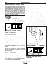
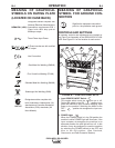
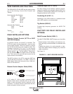
This control provides continuous control of the
machine’s output voltage and current from mini-
mum to maximum (typical full pot range between
15 to 44 volts and 90 to 750 amps) as it is rotated
clock-wise. Voltage or current control is deter-
mined by setting of Mode Switch (CV or CC).
"('#(''% !&"!% "'&D6A05
When this switch is in the REMOTE “ ” posi-
tion, the IDEALARC® DC-600 VRD’s output termi-
nals will be electrically “cold” until a remote device
such as a wire feeder closes the #2 and #4 circuit
in the MS-receptacle or terminal strip (T.S.2).
When this switch is in the ON “ ” position the
machine’s output terminals will be electrically
energized all the time.
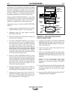
"% "'&D6A05
When this switch is set to the LOCAL “ “ posi-
tion, control of the output voltage and current is via
the OUTPUT CONTROL on the IDEALARC® DC-
600 VRD’s control panel. When this switch is set
to the REMOTE “ ” position, control is
through a remote source such as a wire feeder via
the #75, #76, and #77 leads in the MS-receptacle
or terminal strip (T.S.1).
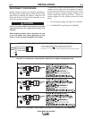
<12&D6A05
This switch allows for selecting the welding
process to be used:
&'-for SMAW and AAC
)&( %%- for SAW
)!!%&- for FCAW and GMAW
)B=92E%202=A.0922?AG <129@
This receptacle provides up to 15 amps of 115
VAC auxiliary power.
):=6?0B6A?2.82?
This breaker protects the 115 VAC auxiliary cir-
cuits located in the duplex receptacle, terminal
strip (T.S.2) and MS-receptacle.
):=6?0B6A?2.82?
This breaker protects the 42VAC auxiliary circuits
located in the terminal strip (T.S.2) and MS-recep-
tacle.
#6; &%202=A.092
This connector provides easy connection for a
wire feeder control cable. It provides connections
for auxiliary power, output switching, remote out-
put control, wire feeder voltmeter sense lead and
ground. Refer to 14 Pin MS Type Receptacle in
the Installation Section for information about the
circuits made available at this receptacle.
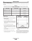
'2?:6;.9&A?6=<C2?#.;29
Rotate this panel to gain access to the circuits
made available at the two terminal strips (T.S.1
and T.S.2). These terminal strips contains the
same circuits as the 14 pin MS-receptacle. There
is a box connector adjacent to this cover for rout-
ing leads to the terminal strips.
!24.A6C2"BA=BA'2?:6;.9
This output terminal is for connecting a welding
cable. To change welding polarity and for proper
welding cable size refer to Electrode and Work
Cables in the Installation Section.
#<@6A6C2"BA=BA'2?:6;.9
This output terminal is for connecting a welding
cable. To change welding polarity and for proper
welding cable size refer to Electrode and Work
Cables in the Installation Section.
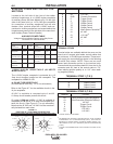
)%645A@
When VRD is active, in CC mode, these lights
illuminate based on the stud voltage while weld-
ing. The green light will be on when the welding
voltage is under 30 volts and the red light light will
turn on when the voltage is 30 volts or greater.
'52?:.9#?<A20A6<;645A";9F<;<12@
.;1
An amber light on the machine control panel indi-
cates when either of the two protective ther-
mostats has opened. Output power will be dis-
abled temporarily. Thermostat will automatically
reset when the machine cools to an acceptable
operating temperature.
(+%, #"*% ! &%#
'
42 volt AC auxiliary power, as required for some wire
feeders, is available through the wire feeder MS-
receptacle. A 10 amp circuit breaker protects the 42
volt circuit from overloads.
On Codes and , IDEALARC® DC-600
VRD machines supply 115 volt AC auxiliary power
through the wire feeder receptacle. A 15 amp circuit
breaker protects the 115 volt circuit from overloads.