


% &
%J)%
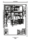
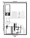
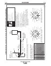
N.C. Tape up bolted connection if lead #21 is extended.
N.D. Connect the control cable ground lead to the frame terminal
marked near the power source terminal strip. The power
source grounding terminal (marked and located near the power
source input power connections) must be properly connected to
electrical ground per the power source operating manual.
N.E. If an optional remote voltage control is used, connect it to
this terminal strip.
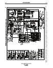
N.A. Welding cables must be of proper capacity for the current and
duty cycle of immediate and future applications. See LN-7
Operating Manual for proper sizes.
N.B. If LN-7 is equipped with a meter kit, extend LN-7 control cable
suitable for the installation. An S16586-[LENGTH] remote
voltage sensing work lead may be ordered for this purpose.
Connect it directly to the work piece independent of the welding
work cable connection. For convenience, this extended #21 lead
should be taped to the welding work lead. (If the length of
welding work cable is short, less than 25 feet, and connections
can be expected to be reliable, then control cable lead #21 does
not need to be extended and can be directly connected to
terminal #21 on the terminal strip. Note that this is not the
preferred connection because it adds error to the LN-7 voltmeter
Above diagram shows electrode connected positive. To change polarity,
turn power off, reverse the electrode and work leads at the power
41
4231
32
7576
77
NEGATIVE
POSITIVE
32
31
2
4
GND
21
N.A.
N.D.
ELECTRODE CABLE
TO WIRE FEED UNIT
TO WORK
POWER SOURCE
N.E.
N.F.
reading.)
N.F.
If lead #21 is to be connected to
the terminal strip,
connect to the #21 terminal that matches
work polarity. This
connection must be changed whenever the
electrode polarity is
changed.
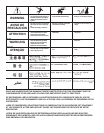
Only qualified persons should install, use or
service this machine.
Do not operate with covers removed.
Disconnect power source before
servicing.
Do not touch electrically live parts.
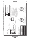
LN-7 TO INPUT
CABLE PLUG
LN-7 CONTROL
CABLE
21
-
21
FOR CONTROL CABLE
WITH 14 PIN
MS-TYPE
PLUG CONNECTOR
OR
FOR CONTROL CABLE
WITH TERMINAL STRIP
LEAD CONNECTORS
CONTROL CABLE
S22976
source and position the switch on wire feeder (if equipped )
to proper polarity. Also refer to note N.F.
N.B. & N.C.
14-PIN
RECEPTACLE
lead #21 from control cable with terminal strip connectors or from
14-pin receptacle using #14 AWG or larger insulated wire physically
21
+
REMOTE VOLTAGE SENSING LEAD
10-30-98F
N.G.
N.G. Illustration does not necessarily represent actual position of
for more information.
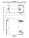
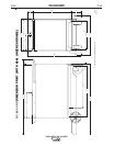
CONNECTION OF LN-7 TO THE DC-600 VRD POWER SOURCE
appropriate output studs. Refer to power source operating manual
For proper setting of switches on power source,
see power source operating manual.
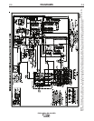
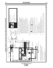
N.C. Tape up bolted connection if lead #21 is extended.
N.D. Connect the control cable ground lead to the frame terminal
marked near the power source terminal strip. The power
source grounding terminal (marked and located near the power
source input power connections) must be properly connected to
electrical ground per the power source operating manual.
N.E. If an optional remote voltage control is used, connect it to
this terminal strip.
N.A. Welding cables must be of proper capacity for the current and
duty cycle of immediate and future applications. See LN-7
Operating Manual for proper sizes.
N.B. If LN-7 is equipped with a meter kit, extend LN-7 control cable
suitable for the installation. An S16586-[LENGTH] remote
voltage sensing work lead may be ordered for this purpose.
Connect it directly to the work piece independent of the welding
work cable connection. For convenience, this extended #21 lead
should be taped to the welding work lead. (If the length of
welding work cable is short, less than 25 feet, and connections
can be expected to be reliable, then control cable lead #21 does
not need to be extended and can be directly connected to
terminal #21 on the terminal strip. Note that this is not the
preferred connection because it adds error to the LN-7 voltmeter
Above diagram shows electrode connected positive. To change polarity,
turn power off, reverse the electrode and work leads at the power
41
4 2 31
32
75 76
77
NEGATIVE
POSITIVE
32
31
2
4
GND
21
N.A.
N.D.
ELECTRODE CABLE
TO WIRE FEED UNIT
TO WORK
POWER SOURCE
N.E.
N.F.
reading.)
N.F.
If lead #21 is to be connected to
the terminal strip,
connect to the #21 terminal that matches
work polarity. This
connection must be changed whenever the
electrode polarity is
changed.
Only qualified persons should install, use or
service this machine.
Do not operate with covers removed.
Disconnect power source before
servicing.
Do not touch electrically live parts.
LN-7 TO INPUT
CABLE PLUG
LN-7 CONTROL
CABLE
21
-
21
FOR CONTROL CABLE
WITH 14 PIN
MS-TYPE
PLUG CONNECTOR
OR
FOR CONTROL CABLE
WITH TERMINAL STRIP
LEAD CONNECTORS
CONTROL CABLE
S22976
source and position the switch on wire feeder (if equipped )
to proper polarity. Also refer to note N.F.
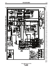
N.B. & N.C.
14-PIN
RECEPTACLE
lead #21 from control cable with terminal strip connectors or from
14-pin receptacle using #14 AWG or larger insulated wire physically
21
+
REMOTE VOLTAGE SENSING LEAD
10-30-98F
N.G.
N.G. Illustration does not necessarily represent actual position of
for more information.
CONNECTION OF LN-7 TO THE DC-600 VRD POWER SOURCE
appropriate output studs. Refer to power source operating manual
For proper setting of switches on power source,
see power source operating manual.