


#"%'%"(&""'!(
%! #"%
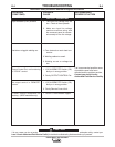
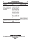
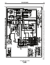
1. All 10 LED’s must be ON when the POWER
SOURCE is turned “ON” and the trigger circuit* is
closed.
2. LED’s 7, 8, and 9 indicate AC power being supplied
to the P.C. board from auxiliary windings on the
main transformer (T1). If a LED is not “ON”, turn the
machine off and unplug P5 from the firing board.
Turn the machine back on and check the following
voltages:
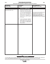
3. If all voltages are present, turn power off, and plug
P5 back into J5. Turn power back on. If LED’s are
still “OUT”, replace Firing P.C.B.
4. If voltages were not present then check the wiring
back to the auxiliary windings for a possible open.
5. LED 10 senses when trigger circuit* is closed.
Close trigger circuit, LED10 should be on be “ON”.
Open trigger circuit, LED 10 should be “OFF”. If
LED does not come “ON”, check to make sure
leads 2,4, or 41 are not broken.
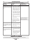
6. LED’s 1 through 6 indicate gate signals are being
sent to the main SCR’s 1 through 6 respectively. If
LED 5 (located on Control Board) is “ON”, along
with LED’s 7, 8, and 9 (on Firing P.C.B), and LED’s
1 through 6 are “OFF”, check to make sure lead
231 between Control board and Firing board is
not broken
7. If any one of LED’s 1 through 6 are “OFF” and
LED’s 7, 8, and 9 are “ON”, replace the Firing
P.C.B.
#"% '%"(&""'! (
"!'%"#"%
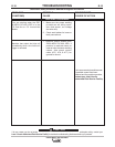
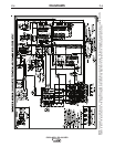
1. LED 1 indicates AC input voltage necessary to gen-
erate the DC supply voltages is present. These volt-
ages power the Control board circuitry. If LED 1 is
not “ON” when machine POWER is “ON”, check
leads 255, 256, X1, and X2 for broken connection.
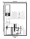
'%"(&""'!
%J)%
Observe all Safety Guidelines detailed throughout this manual
If for any reason you do not understand the test procedures or are unable to perform the tests/repairs safely, contact your
<0.96;0<9;BA5<?6G216291&2?C602.0696AF for technical troubleshooting assistance before you proceed.
('"!
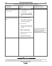
Voltage across leads 255 and 256 should be
approximately 115VAC. Check voltage across sec-
ondary winding of the control transformer (T2) which
supplies leads 255 and 256. Measure +16VDC from
TEST POINTS “A” to “C” and -10VDC from TEST
POINTS “A” to “J” on Control board.
2. LED 2 indicates welder output voltage is being sup-
plied to the control circuit. LED 2 will be “ON”
brightly in CC STICK mode with trigger circuit*
closed and no load. (LED 2 diminishes in bright-
ness as output voltage is reduced). If LED 2 is not
“ON”, look for open connection in lead 222 circuit.
3. LED 3 indicates power is being applied to FAULT
PROTECTION RELAY (CR2). LED 3 will be “ON”
when machine POWER is “ON”. LED 3 goes “OUT”
when CR2 drops out which turns off the INPUT
CONTACTOR (CR1). When LED 3 goes out, LED 4
comes “ON”. See step 3.
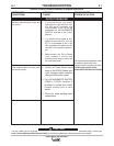
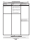
4. LED 4 indicates an overload or fault condition; LED
should not be on. If this LED comes “ON”, the
INPUT CONTACTOR (CR1) will turn off and the red
POWER light stays illuminated. This was do to
either a short across output, or a current draw in
excess of 780A, or leads 75, 76, or 77 grounded to
negative output lead. Remove short or reduce out-
put current or eliminate ground. Welder must be
reset by turning POWER ON/OFF switch to “OFF”
and then back to “ON”. If no short or loads above
780A exists or no ground, replace Control P.C.B.
5. LED 5 indicates DC control voltage (which supplies
Firing board) is present. LED 5 will be “ON” in CV
INNERSHIELD mode with trigger circuit* closed,
CONTROL POT at minimum, and no load. (LED 5
diminishes in brightness as output voltage is
increased). Replace P.C. board if LED 5 did not go
“ON”.
6. LED 6 indicates trigger circuit* condition. LED 6
“ON” indicates trigger circuit is closed. LED 6 “OFF”
indicates trigger circuit is open. If LED 6 does not
come “ON”, when trigger circuit closed, look for
open connections in the 2 & 4 circuit and in leads
290 and 291.
TRIGGER CIRCUIT is closed by any of the following:
• Wire feeder’s trigger is closed.
• A jumper is placed across 2 & 4 on terminal strip
T.S.2. or across pins C & D in 14 pin connector.
• OUTPUT TERMINAL switch is in the “ON” position.
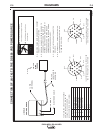
LED that
was off
7
8
9
Check AC voltage between pins specified,
it should be approximately 32VAC .
P5 pins 15 & 16 (wires 203,204)
P5 pins 7 & 8 (wires 205,206)
P5 pins 5 & 6 (wires 207,208)