


A-5
INSTALLATION
MAXsa™ 10 CONTROLLER
A-5
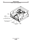
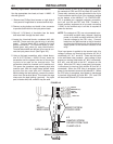
Auxiliary Input Power Connection Instructions
Use the appropriate size leads, at least 14 AWG – 2
wire with ground.
1. Remove two Phillips Head screws on right side of
front panel of hinged door to access terminal strip.
2. Remove a plug button and install a box connector
to provide strain relief for the input power leads.
3. Strip off 1/4”(6.4mm) of insulation from the leads
and route them through the strain relief
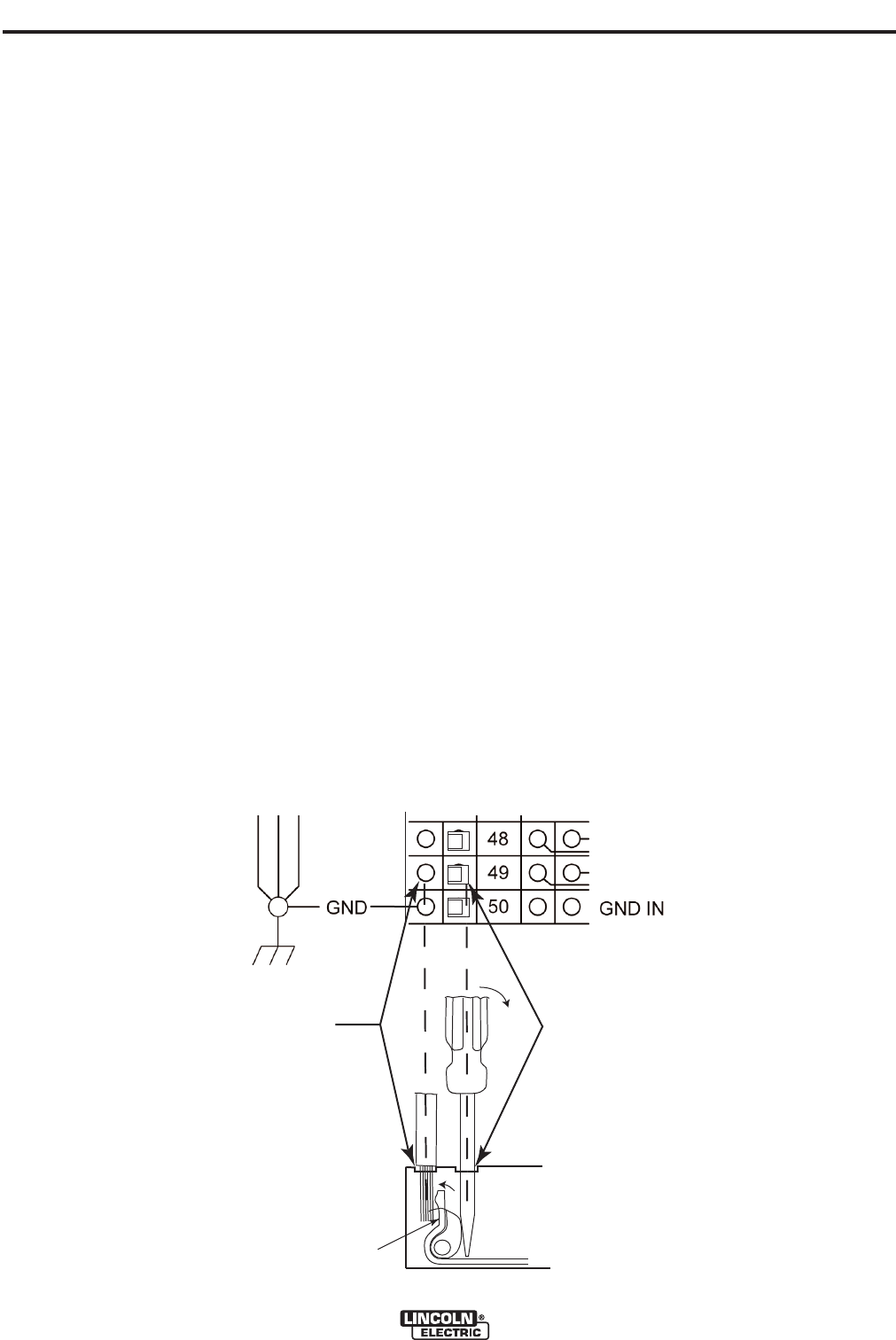
4. Locate the 4-terminal blocks, numbered #48, #49,
and #50. These are to be used to bring in auxiliary
power. Terminal block #50 is used for the input
ground connection. This terminal block is color-
coded green and yellow for easy identification.
Terminal blocks #48 and #49 are to be used to con-
nect the input power circuit. (See Figure A.3).
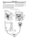
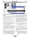
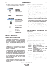
5. Using a flat-head screwdriver with a blade dimen-
sion of 0.137"(3.5mm) x 0.020"(.51mm), insert the
screwdriver into the square hole next to the mount-
ing hole to be used on the terminal strip. The
screwdriver should be inserted until it bottoms out.
This opens the screwless cage clamping style wire
insertion port. With the cage clamp opened insert
the wire into the round port until it bottoms out.
While holding the lead securely, remove the screw-
driver from the terminal block. This closes the cage
clamp onto the lead holding it securely. Any open
port on blocks #48, #49, and #50 may be used.
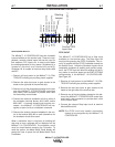
Terminal blocks 48 and 49 are shipped connected to
the contacts of CR2 and CR3 by leads 531 and 532.
These relay contacts are also connected to the 4-pin
Travel connector and the 3-pin Flux connector located
on the bottom of the MAXsa™ 10 CONTROLLER.
CR1 is available for a separate customer connection,
but it will turn ON and OFF with CR2. Therefore, if
Lincoln auxiliary equipment is to be used, connecting
115VAC to the terminal strip is all that is required to
power the devices.
NOTE: The contacts of CR1 are not connected to ter-
minals #48 and #49 when shipped. Applying
power to the #48 and #49 terminals will not
transfer voltage to the CR1 relay. Connect
leads from the #48 terminal to the #4 terminal
and from the #49 terminal to the #3 terminal to
supply power to the common contacts of the
relay.
Once input power is applied to the terminal strip, this
voltage is always on terminal strip blocks #3, #4 (if
connected), #11, #17, and #18. These are the inputs
to the solid-state relay contacts. Input voltage is also
present on terminal strip blocks #7, #8 (if connected),
#15, #21, and #22 due to the N.C. contacts on the
relays. When the CR1 relay is energized, input power
is transferred to terminal strip blocks #5 and #6 (if
connected). When the CR2 relay is energized, input
power is transferred to terminal strip block #13. When
the CR3 relay is energized, input power is transferred
to terminal strip blocks #19 and #20. CR1 and CR2
will be turned ON and OFF at the same time.
INSERT
WIRE HERE
INSERT SCREW
DRIVER HERE
# 1
# 3
REMOVE SCREW
DRIVER FROM CAGE
CLAMP HOLE.
# 2
CAGE CLAMP
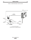
VAC IN
NEUTRAL (31)
VAC IN
LINE (32)
FIGURE A.3