


A-7
INSTALLATION
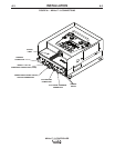
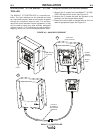
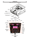
MAXsa™ 10 CONTROLLER
A-7
SHUTDOWN INPUTS
The MAXsa™ 10 CONTROLLER has two shutdown
inputs available on the terminal strip. These are inde-
pendent, normally closed inputs that can be used for
limit switches, PLC inputs, etc, in order to shut down
the welding operation for any reason. Shutdown #1 is
located on terminal strip blocks #24 and #25.
Shutdown #2 is located on terminal strip blocks #26
and #27.
1. Remove all input power to the MAXsa™ 10 CON-
TROLLER including any auxiliary power supplies.
2. Remove the wire duct cover to gain access to the
leads on the right side of the terminal strip.
3. Remove one of the plug buttons located on the bot-
tom of the MAXsa™ 10 CONTROLLER control box
and install a box connector to provide strain relief
for the auxiliary control leads.
4. Connect the external shutdown circuit to either of
the shutdown terminal blocks, #24 & #25, and/or
#26 & #27. A normally closed circuit must be con-
nected – the MAXsa™ 10 CONTROLLER will rec-
ognize an open circuit as a shutdown command.
5. Remove the shorting jumpers imbedded in the cen-
ter of the terminal strip with a small screwdriver for
the shutdown circuits to be used.
When a shutdown input is received, all welding will
stop and an error message will be displayed on the
MAXsa™ 10 CONTROLLER. The shutdown circuit
must be closed before resetting the Controller. To
reset the system, the Mode Select Panel display will
prompt the user to press the left Mode Select Panel
Pushbutton.
STOP INPUT
The MAXsa™ 10 CONTROLLER has a Stop Input
available on the terminal strip. The Stop Input will
work just like pressing the STOP Pushbutton. This cir-
cuit is in parallel with the STOP Pushbutton located on
the Switch Panel. Unlike the Shutdown Inputs, which
completely shutdown all welding and auxiliary equip-
ment, the STOP Input will allow all welding and auxil-
iary motion to continue based on the END OPTIONS
configurations in the MAXsa™ 10 CONTROLLER.
See Figure A.5.
1. Remove all input power to the MAXsa™ 10 CON-
TROLLER including any auxiliary power supplies.
2. Remove the wire duct cover to gain access to the
leads on the right side of the terminal strip.
3. Remove one of the plug buttons located on the bot-
tom of the MAXsa™ 10 CONTROLLER control box
and install a box connector to provide strain relief
for the control leads.
4. Connect the external Stop Input circuit to terminal
blocks #39 and #41.
NOTE: The STOP circuit only needs a momentary
closure to be recognized by the MAXsa™ 10
CONTROLLER.
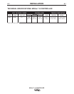
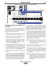
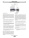
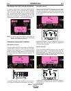
FIGURE A.5 - SHUTDOWN AND STOP INPUTS
859
FLUX GND
CR3 NC #7
SHUTDOWN #2 SUPPLY
SHUTDOWN #1
SHUTDOWN #1 SUPPLY
22
23
24
25
26
27
8510
859
CR3-7
GND-C
8511
SHUTDOWN #2
Shorting
Jumper
Connect STOP
Input Here
39
41
40
SWITCH GROUP #1 SUPPLY
START
STOP