


A-2
INSTALLATION
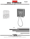
MAXsa™ 10 CONTROLLER
A-2
SAFETY PRECAUTION
WELDING VOLTAGE
Wire feed parts are electrically live while welding and
while inching wire (with Touch Sense feature selection).
The electrically live parts are listed below:
Electrode Electrode Reel
Wire Drive Motor Drive Rolls
Gear Box Cross-seam Adjuster
Wire Straightener Welding Nozzle
Welding Cables Welding Cable Terminal
• Do not touch electrically live parts or
electrodes with your skin or wet clothing.
• Insulate yourself from the work and
ground.
• Always wear dry insulating gloves.
MECHANICAL HAZARDS
• Welding fixture or wire feeder will move during
welding or inching. Keep away from pinch
points.
• Electrode reel and drive rolls turn during
welding or inching. Keep gloved hands
away from areas that may catch the
glove.
----------------------------------------------------------------------------------------
LOCATION AND MOUNTING
The MAXsa™ 10 CONTROLLER will operate in harsh
environments and can be used outdoors with an IP 23
rating. Even so, it is important that simple preventative
measures are followed in order to assure long life and
reliable operation. The MAXsa™ 10 CONTROLLER
must be mounted in the vertical(upright) position and
located where there is little risk of impacts to the
Controller.
ELECTRIC SHOCK can kill.
• Only a qualified electrician should
connect the MAXsa™ 10 CON-
TROLLER. Installation should be
made in accordance with the
appropriate National Electrical
Code, the local codes and the infor-
mation in this manual.
• Turn off the input power to the
power source at the disconnect
switch or fuse box before working
on this equipment. Turn off the
input power to any other equipment
connected to the welding system at
the disconnect switch or fuse box
before working on this equipment.
• Do not touch electrically hot parts.
----------------------------------------------------------------------------------------
HIGH FREQUENCY PROTECTION
Locate the MAXsa™ 10 CONTROLLER away from radio
controlled machinery. The normal operation of the
MAXsa™ 10 CONTROLLER may adversely affect the
operation of RF controlled equipment, which may result in
bodily injury or damage to the equipment.
AUXILIARY EQUIPMENT INPUT POWER
CONNECTION
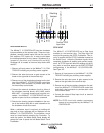
The MAXsa™ 10 CONTROLLER has the ability to control
auxiliary equipment such as feeders, flux hoppers and
travel motors using solid state relays. There are three
relays (CR1,CR2 &CR3) in the MAXsa™ 10 CON-
TROLLER, controlled by two independent coil drivers. The
coils of CR1 and CR2 are in parallel, therefore, they must
turn ON and OFF at the same time. The CR1 and CR2
relays are designated for driving travel motors to control
motion. CR3 is driven separately, and is designated to
control flux hopper operation.
MAXsa™ 10 CONTROLLER Relay Ratings:
Coil: 12Vdc, resistance = 86 ohms at 25° C
Normally Closed (N.C.) Contacts: 3A @ 277VAC
Normally Open (N.O.) Contacts: 30A @ 277VAC
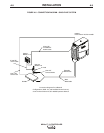
The MAXsa™ 10 CONTROLLER does not provide the
input power to feed any equipment, other than the MAXsa
22 or the MAXsa 29 feeders. Therefore a separate power
feed must be provided by the end user. The MAXsa™ 10
CONTROLLER has been shipped standard with all of the
wiring and connectivity to operate the Lincoln K325 TC-3
Travel Carriage (4-pin cable connector) and the Lincoln
K219 Automatic Flux Hopper (3-pin cable connector). The
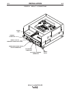
CR2 Relay is wired to the 4-pin travel connector, and the
CR3 Relay is wired to the 3-pin flux connector, both locat-
ed on the bottom of the MAXsa™ 10 CONTROLLER.
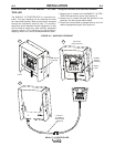
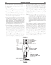
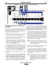
If either of these is to be used with the MAXsa™ 10 CON-
TROLLER, the end-user must provide the 115VAC input
power to the terminal strip located inside the MAXsa™ 10
CONTROLLER. Access to the terminal strip may be
obtained via one of the two .875” dia. (22.2mm) access
holes in the bottom of the MAXsa™ 10 CONTROLLER.
These access holes are shipped with plug buttons
installed. Remove the plug button and install a suitable
strain relief to protect the wires. See Figure A.1
Although input power to MAXsa™ 10 CONTROLLER is
turned off, the customer installed auxiliary input may
be energized! Ensure that all input power to the
MAXsa™ 10 CONTROLLER is turned off before open-
ing the cover
----------------------------------------------------------------------------------------
WARNING
WARNING
CAUTION