


E-2
TROUBLESHOOTING
E-2
MAXsa™ 10 CONTROLLER
Observe all Safety Guidelines detailed throughout this manual
If for any reason you do not understand the test procedures or are unable to perform the tests/repairs safely, contact your
Local Lincoln Authorized Field Service Facility for technical troubleshooting assistance before you proceed.
CAUTION
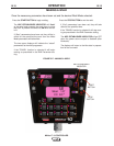
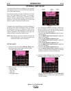
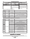
USING THE STATUS LED TO TROUBLESHOOT
SYSTEM PROBLEMS
The MAXsa 10 is equipped with a Status Light. If a problem occurs it is
important to note the condition of the status lights. Therefore, prior to
cycling power to the system, check the power source status light
for error sequences as noted below.
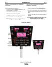
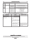
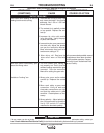
Included in this section is information about the power source and
Wire Drive Module Status LED’s, and some basic troubleshooting
charts for both machine and weld performance.
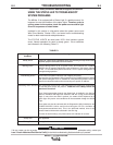
The STATUS LIGHTS are dual-color LED’s that indicate system
errors. Normal operation for each is steady green. Error conditions
are indicated in the following Table E.1.
Light
Condition
Steady Green
Blinking Green
Fast Blinking Green
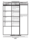
Alternating Green and Red
Steady Red
Blinking Red
Meaning
System OK. Power source is operational, and is communicating normally with all healthy
peripheral equipment connected to its ArcLink network.
Occurs during power up or a system reset, and indicates the POWER
WAVE® i400 is mapping (identifying) each component in the system. Normal
for first 1-10 seconds after power is turned on, or if the system configuration is
changed during operation.
Under normal conditions indicates Auto-mapping has failed.
Also used by the Diagnostics Utility (included on the POWER WAVE® Utilities
and Service Navigator CD’s or available at www.powerwavesoftware.com) to
identify the selected machine when connecting to a specific IP address.
Non-recoverable system fault. If the Status lights are flashing any combination
of red and green, errors are present. Read the error code(s) before the
machine is turned off.
Error Code interpretation through the Status light is detailed in the Service
Manual. Individual code digits are flashed in red with a long pause between
digits. If more than one code is present, the codes will be separated by a
green light. Only active error conditions will be accessible through the Status
Light.
Error codes can also be retrieved with the Diagnostics Utility (included on the
POWER WAVE® Utilities and Service Navigator CD’s or available at
www.powerwavesoftware.com). This is the preferred method, since it can
access historical information contained in the error log.
To clear the active error(s), turn power source off, and back on to reset.
Not applicable.
Not applicable.
TABLE E.1