


A-4
INSTALLATION
SYNERGIC 7 & 7H
A-4
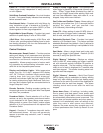
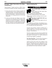
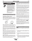
Keypad - Seven key, membrane
type with “snap” tactile feel and
embossed domes. Long life
design. Spatter resistant surface.
Display - 3-1/2 digit 7-segment
LED with (+) or (-) polarity indica-
tors. .56” (14.2mm) character
height. Displays arc voltage in
volts, wire speed in IPM or m/m and
all timers in seconds.
Indicator Lights - Extra bright red
LED’s for viewing at almost any
angle. Always indicates the mode
being used and which function or
timer is being displayed.
Function Select key enables operator to choose which
function will be displayed as shown by the appropriate
indicator light. Pressing the key causes lights to sequence
(top to bottom) starting from the current indicated position.
The function displayed will be adjustable with the rotating
encoder controls or arrow keys:
Adjusting either encoder knob automatically transfers dis-
play (and indicator light) to the function being adjusted.
Top Light - Indicates display of preset voltage or percent
trim when not welding and arc voltage while welding (as
indicated by top light “blinking”), and continues for 5 sec-
onds after the weld has stopped (memory vpltmeter). The
power source automatically determines whether preset
voltage or percent trim will be displayed, and adjustable
with Volts/Trim rotating encoder control.
Middle Light - Indicates Run-in speed is being displayed.
As shipped, these models are setup for a 50 IPM
(1.27m/min) fixed run-in speed with display function deac-
tivated. They may be user-selected to activate or deacti-
vate adjustable Run-in display, and setting with arrow
keys.
Bottom Light - Indicates Weld Feed Speed (WFS) is being
displayed, and is adjustable with the Wire Feed Speed
rotating encoder control. If selected, this light will “blink”
while welding, indicating that the display has been select-
ed to display welding amps, and continues for 5 seconds
after the weld is stopped (memory ammeter).
Timer/Crater Select
key enables operator to choose spot
or gas timers, or crater speed as indicated by the appro-
priate light. Pressing the key causes lights to sequence
(left to right, top to bottom) starting from the current indi-
cated selection. Any parameter not available in the mode
selected is skipped over.
Top Left Light - indicates preflow time is being displayed in
seconds.
Top Right Light - indicates postflow time is being dis-
played in seconds.
Middle Light - indicates Crater Feed Speed is being dis-
played. This display will only occur if 4-step mode with
crater fill is selected.
Bottom Light - indicates spot on time is being displayed in
seconds.
Increase arrow key increases the setting of the para-
meter selected to be displayed. Arrow keys do not
function for Wire Feed Speed or Volts/Trim settings,
which are adjusted using the rotating encoder knobs.
Decrease
arrow key decreases the setting of the para-
meter selected to be displayed. Arrow keys do not
function for Wire Feed Speed or Volts/Trim settings,
which are adjusted using the rotating encoder knobs.
Cold Feed key energizes the wire
feeder but not the power source or
solenoid valve. Cold feed speed is
adjustable and is displayed only
while pressing Cold Feed, and the
last speed selected is stored in
memory for the next Cold feeding.
Gas Purge
key energizes the sole-
noid valve but not the wire feeder or
power source.
Mode Select
key enables operator
to choose mode of operation shown
by the indicator lights. Pressing key
causes mode lights to sequence
(top to bottom) starting from the
current indicated selection.
Top Light - Indicates 2-step (stan-
dard) trigger mode.
Middle Light - Indicates 4-step
(lock) trigger mode. This mode may
be selected to include crater fill or
weld current interlock.
Bottom Light - Indicates spot weld
mode.
V
1
2
COLD FEED GAS PURGE
WFS
PREFLOW
POSTFLOW
SPOT
STD
LOCK
SPOT
RUN-IN
2-STEP
4-STEP
CRATER
TRIM
/
VOLTS
L9571-1
V
WFS
RUN-IN
TRIM
/
VOLTS
1
2
SPOT
CRATER
STD
LOCK
SPOT
2-STEP
4-STEP
COLD FEED
GAS PURGE
KEYPAD AND DISPLAY
DESCRIPTION