


E-5
TROUBLESHOOTING
E-5
SYNERGIC 7 & 7H
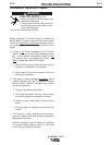
Observe all Safety Guidelines detailed throughout this manual
If for any reason you do not understand the test procedures or are unable to perform the tests/repairs safely, contact your
Local Lincoln Authorized Field Service Facility for technical troubleshooting assistance before you proceed.
CAUTION
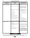
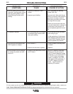
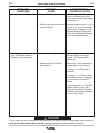
PROBLEMS
(SYMPTOMS)
POSSIBLE
CAUSE
RECOMMENDED
COURSE OF ACTION
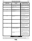
9. Wire feed motor runs and solenoid
turns on but no arc voltage pre-
sent.
10. Speed does not change when
weld current flows.
11. Voltmeter does not function or
read properly when arc voltage is
present.
a. Power source is defective.
b. Input cable is defective.
c. Wiring harness or Control PC
board is defective.
a. Run-in and weld speeds are set
to the same value or run-in is set
to ---.
b. Power Source may be defective
or there may be a problem with
the Serial communications.
a. Electrode sensing lead or connec-
tions may be intermittent.
b. Serial communication problem.
a. If arc voltage is present when wire feeder is
connected to the other input receptacle (#1 or
#2) of power source then power source is
defective. Otherwise, select a stick procedure
on power source, connect a known good input
cable (see step b) to wire feeder #1 receptacle
of power source, and jumper across sockets C
and D of 8-socket input cable plug. If no arc
voltage is present (refer to display on power
source) then power source is defective.
b. Disconnect input cable from power source and
wire feeder. Check continuity between socket
C of 8-socket plug and pin C of 14-pin plug of
the input cable, and between socket D of 8-
socket plug and pin D of 14-pin plug of the
input cable. Replace cable if no continuity.
c. Check continuity between pin C of 8-pin recep-
tacle and pin 7 of plug P1, and between pin D
of 8-pin receptacle and pin 6 of plug P1. If no
continuity then harness is faulty, otherwise
replace Control PC board. (See procedure for
replacing PC boards.)
a. Set run-in and weld speeds to desired set-
tings.
b. Make sure that parameters on power source
display, such as WFS, match those on wire
feeder display. If not, refer to Problem 14.
Otherwise, replace control PC board. (See
procedure for replacing PC boards.)
a. Check continuity from brass block on wire
feeder to pin F of 8-pin control cable recepta-
cle on wire feeder. If there is no continuity,
repair faulty connection.
b. Make sure that parameters on power source
display, such as WFS, match those on wire
feeder display. If not, refer to Problem 14.
Otherwise, replace Control PC board. (See
procedure for replacing PC boards.)