


E-11
TROUBLESHOOTING
E-11
SYNERGIC 7 & 7H
If for any reason you do not understand the test procedures or are unable to perform the tests/repairs safely, contact your
Local Lincoln Authorized Field Service Facility for technical troubleshooting assistance before you proceed.
CAUTION
Observe all Safety Guidelines detailed throughout this manual
PROBLEMS
(SYMPTOMS)
POSSIBLE
CAUSE
RECOMMENDED
COURSE OF ACTION
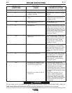
24. Display shows any of the following:
HI
---
HXX
Er
EXX
EP
uP
GLP
a. Voltmeter function is selected and arc
voltage is > 80 VDC.
a. Run-in speed is selected but is dis-
abled.
a. See Problem 5 or see Section on
Safety Precautions.
a. EEPROM error.
a. Where XX is a number from 1 to 10.
System error.
a. EPROM checksum error.
a. Microprocessor RAM error.
a. Grounding Lead Protector circuit is
activated, due to excessive current
flow into the wire feeder frame.
b. Faulty GLP reed switch, harness, or
Control PCB.
a. Normal operation. Voltmeter only reads 0-
80 VDC.
a. Run-in speed is now = weld speed. To re
enable Run-in speed simply press the
increase arrow key.
a. XX indicates time in seconds before unit
will automatically reset.
a. Parameter recalled at power-up was out of
range. Press any key to reset. Check all
settings before proceeding to weld. If this
condition persists then ROM assembly X8
on the Control PC board is faulty. Replace
Control PC board. (See procedure for
replacing PC boards.)
a. Turn off power to feeder. Wait for 5 sec-
onds. Turn power back on. If EXX is dis-
played again then ROM assembly X8 on
the Control board is faulty. Replace
Control PC board. (See procedure for
replacing PC boards.)
a. Turn off power to feeder. Wait 5 seconds.
Turn power back on. If EP is displayed
again then ROM assembly X8 on Control
PC board is faulty. Replace Control PC
board. (See procedure for replacing PC
boards.)
a. Turn off power to feeder. Wait 5 seconds.
Turn power back on. If uP is displayed
again then ROM assembly X8 on the
Control PC board is faulty. Replace
Control PC board. (See procedure for
replacing PC boards.
a. To return to normal operating mode,
release the trigger, and press any key on
the keypad. If "GLP" is still displayed or if
it appears again before the trigger is
closed then proceed to step b. Otherwise,
before proceeding to weld make sure that
the electrode is not touching the wire feed-
er frame.
b. Replace GLP reed switch CR1 if it is
shorted. Check the wiring harness
between GLP reed switch CR1 and the
Control board. Repair or replace faulty
harness. If the reed switch and the wiring
harness are both OK then replace the
Control board.