


B-4
OPERATION
B-4
Procedure Selector Switch
The toggle switch on the front panel provides selection
of Procedure A or Procedure B, as set with the front
panel knob controls. Rotating the knob encoder
changes only the procedure selected by this switch.
Also, this switch selects the A or B memory pair select-
ed at the Power Wave power source.
NOTE: The dual procedure overlay must be present
on the Power Wave power source for the Procedure
Selector switch to function. If this overlay is not
used, only Procedure A will be selected no matter
what position the Procedure switch is in.
Setting the toggle switch to the center “Gun Switch”
position permits the Procedure A or Procedure B to be
selected by the optional K683-1 Dual Procedure
Switch. The K1449-1 Dual Procedure Remote Control
can be used with this panel Procedure Switch in any
position.
Dual Procedure Remote Control (K1449-1)
When this option is connected to the feeder control
receptacle the front panel knob controls are disabled
and procedure control is transferred to the knob
encoder controls of the remote, which function in the
exact same manner.
NOTE: The dual procedure overlay must be pre-
sent on the Power Wave power source for the
Procedure Selector switch to function. If this
overlay is not used, only Procedure A will be
selected no matter what position the Procedure
switch is in.
If using the optional K683-1 Dual Procedure Switch to
select A or B along with the remote, both the front
panel and remote Procedure selector switches must
be set to “Gun Switch” (center) position.
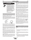
SYNERGIC 7 & 7H
4-Step Trigger Mode
Selection
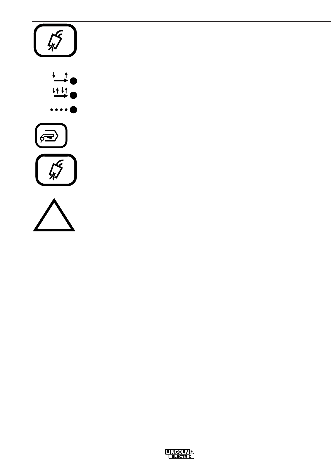
Pressing both the Gas Purge key
and then the Trigger mode select
key causes the 4-step mode light to
turn on and will toggle the 4-step
trigger mode between:
4-step with current interlock (as shipped)
Crater light will not turn on.
and
4-step with crater fill.
Crater light will turn on for crater speed set-
ting with arrow keys.
(See Mode Selection and Display
Control Keys sections).
Memory Ammeter Selection
Pressing both the Gas Purge key
then the Up Arrow key at the same
time causes the WFS light to “blink”
for about 3 seconds while display
shows weld amps reading with elec-
trode polarity symbol. This indicates
that while welding, the display will
show welding amps, indicated by
“blinking” WFS indicator light, which
continues for 5 seconds after the
weld is stopped (memory ammeter)
before returning to displaying WFS
(light not “blinking”.)
Pressing both the Gas
Purge and Up Arrow key again,
returns WFS display to wire speed
while welding.
STD
LOCK
SPOT
2-STEP
4-STEP
GAS PURGE
GAS PURGE