


B-2
OPERATION
B-2
SYNERGIC 7 & 7H
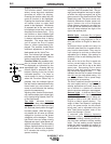
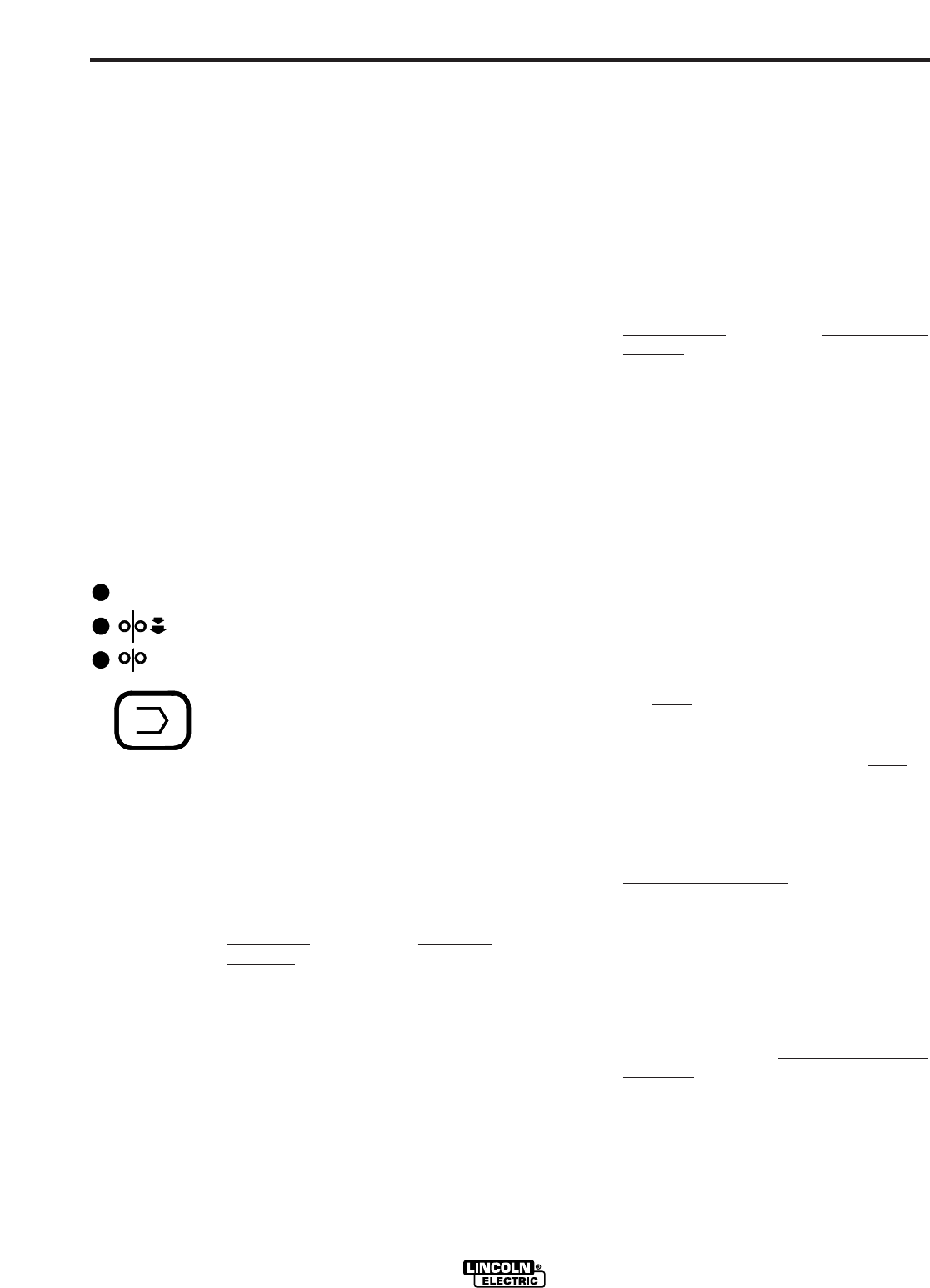
Display Control Keys
The function select, timer/crater
select, arrow keys and rotational
encoders all effect the display.
Pressing the function select key will
cause a function to be displayed.
Pressing the timer/crater select key
will cause a timer or crater feed
speed to be displayed. Whichever
is pressed last is the one that will
be displayed since they cannot be
displayed simultaneously. Only
one function or timer indicator light
can be on at one time and therefore
it always indicates what is being
displayed. The arrow keys allow
you to adjust the Run-in speed
timer or crater speed being dis-
played. The encoder knobs allow
rotational adjustment of weld wire
feed speed and Arc Volts/Trim.
Note: If an indicator light is skipped, that
parameter may not be enabled. Refer to
section covering that parameter.
Function Select key enables oper-
ator to choose which function will
be displayed as indicated by the
appropriate light. Pressing the key
causes lights to sequence (top to
bottom) starting from the current
indicated position. If a timer or
crater speed is being displayed
when the Function Select key is
pressed, then the indicator light of
the last function selected before the
timer/crater key was chosen will
come on and become the starting
point for the sequencing.
Adjusting either encoder knob automati-
cally transfers display (and indicator light)
to the function being adjusted (Volts/Trim
or Wire Feed Speed).
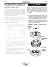
Top Light - indicates Voltmeter
Function has been selected and arc
voltage (in volts) will be displayed along
with electrode polarity when the trigger
has been pressed. When the trigger is
not pressed, this will serve as a preset
voltage/trim function and the preset
voltage/trim will be displayed. The top
light “blinks” when arc voltage is being
displayed and stays lit when preset volt-
age/trim is displayed. The last welding
voltage displayed before the weld is
stopped, will continue to be displayed
for 5 seconds
after welding to permit
operator monitoring.
The preset voltage/trim may be adjusted,
using the Volts/Trim encoder knob. The syn-
ergic preset voltage/trim level may be adjust-
ed within the range synergically set by the
power source for the process and weld Feed
Speed being used.
The power source auto-
matically determines whether preset volt-
age or percent trim will be displayed.
Preset voltage is indicated by one digit only
to the right of the decimal point, while per-
cent trim always displays two digits to the
right of the decimal point.
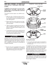
Middle Light
- Indicates Run-In Speed
Function has been selected and the Run-In
speed setting is being displayed in IPM or
m/m (see section for English or Metric dis-
play).
As shipped these models are setup for
minimum rated fixed Run-In speed with dis-
play function deactivated. They may be
user-selected to activate or deactivate
adjustable Run-In display. (See section for
selection of Run-In and resetting fixed Run-
In speed).
Wire will be fed at the Run-In speed rate
until arc current begins to flow. Once arc
current flows, wire will be fed at the Weld
speed rate. Decreasing Run-In speed
below its lower limit (using the down arrow
key) causes the display to read “- - -”. This
indicates that the Run-In speed will be kept
the same
as the weld speed setting. You
can reset a different Run-In speed simply
by pressing the up arrow key.
The Run-In speed will also be the same
as
the weld speed setting if rapid restrike
welding applications are used, where the
arc is restruck in a fraction of a second
after the previous welding arc was stopped.
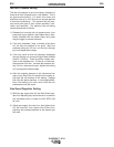
Bottom Light
- Indicates Weld Feed
Speed (WFS) Function has been selected
and the weld speed setting is being dis-
played in IPM or m/m (see section for
English or Metric speed display). The
range of Weld Feed Speed is synergically
set by the power source for the process
being used, and is adjustable using the
Wire Feed Speed encoder knob on the
front of the Synergic 7 Control.
If selected (see Memory Ammeter
Selection section), the bottom light will
“blink” while welding, indicating that the dis-
play has been selected to display welding
amps. The last welding current displayed
before the weld is stopped will continue to
be displayed for 5 seconds after welding to
permit operator monitoring.
V
WFS
RUN-IN
TRIM
/
VOLTS