


A-6
INSTALLATION
SYNERGIC 7 & 7H
A-6
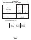
Wire Feed Drive Roll and Guide Tube Kits
NOTE: The maximum sizes the Synergic 7 will feed
satisfactorily are the 3/32” (2.4mm) cored and
1/16” (1.6mm) solid electrodes. The maximum
sizes the Synergic 7H will feed satisfactorily are
the .045 (1.2mm) cored and .045” (1.2mm) solid
electrodes.
The electrode sizes that can be fed with each
roll and guide tube are stencilled on each part.
Check the kit for proper components.
Steel Wire Sizes:
4-Roll
* .068 - 3/32” (1.7 - 2.4mm) Cored KS655-3/32
* 1/16” (1.6mm) Cored or Solid KS655-1/16
.045 - .052” (1.2 - 1.4mm) Solid KS655-052S
.045 - .052” (1.2 - 1.4mm) Cored KS655-052C
.035” (0.9-1.0mm) Cored KS655-035C
.035” (0.9-1.0mm) Solid KS655-035S
.030” (0.8mm) Solid KS655-030S
.023” (0.6mm) Solid KS655-025S
Aluminum Wire Sizes:
1/16” (1.6mm) KS656-1/16A
KS647-1/16A**
3/64” (1.2mm) KS656-3/64A
KS647-3/64A**
.040” (1.0mm) KS647-040A**
.035” (0.9mm) KS656-035A
Drive rolls for only cored
electrode sizes are stencilled
with a “C” suffix to the wire sizes.
Drive rolls for only solid electrode sizes are stencilled
with an “S” suffix to the wire sizes.
Drive rolls for aluminum wire sizes are stencilled with an
“A” suffix to the wire sizes.
* Not for Synergic 7H model.
** For use with Binzel European guns. Installation
instructions are included with these kits. Also
requires K489-2 Fast-Mate Adapter.
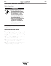
PROCEDURE TO INSTALL DRIVE
ROLL AND GUIDE TUBES
Standard 4-Roll Kits (KS655 and KS656)
1) Turn OFF welding power source.
2) Release both quick release levers by sliding the
levers sideways into the open positions.
3) Remove clamping screw & clamping collar from the
drive shaft closest to the incoming side of the feed-
er.
4) Install drive roll onto keyed shaft. (Do not exceed
the maximum wire size rating of the wire drive.)
Replace collar and tighten clamping screw.
5) Back out the set screw for the middle guide tube.
Install the middle guide tube and slide it up against
the drive roll. DO NOT TIGHTEN THE MIDDLE
GUIDE AT THIS TIME.
6) Install the outgoing drive roll following the same
procedure as steps 3 & 4.
7) Center the middle guide between the two drive rolls
and tighten in place.
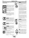
WARNING
Observe all additional Safety Guidelines detailed
throughout this manual.
ELECTRIC SHOCK can kill.
• Do not touch electrically live parts such
as output terminals or internal wiring.
•
When inching with gun trigger, electrode and
drive mechanism are “hot” to work and
ground and could remain energized several
seconds after the gun trigger is released.
• Turn OFF input power at welding power
source before installation or changing
drive roll and/or guide tubes.
• Welding power source must be connected
to system ground per the National
Electrical Code or any applicable local
codes.
• Only qualified personnel should
perform this installation.