E-9
TROUBLESHOOTING
E-9
SYNERGIC 7 & 7H
Observe all Safety Guidelines detailed throughout this manual
If for any reason you do not understand the test procedures or are unable to perform the tests/repairs safely, contact your
Local Lincoln Authorized Field Service Facility for technical troubleshooting assistance before you proceed.
CAUTION
PROBLEMS
(SYMPTOMS)
POSSIBLE
CAUSE
RECOMMENDED
COURSE OF ACTION
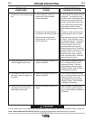
19. Dual procedure switch of remote
control kit is not functioning prop-
erly.
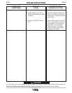
20. Purge key does not turn on sole-
noid but trigger closure does.
21. Cold Feed key does not turn on
wire feed motor but trigger clo-
sure does.
22. Display and/or indicator lights do
not change when the arrow or
select keys are pressed.
a. Local dual procedure switch is not
in "Gun" position, and/or an
optional gun dual procedure
switch is attached.
b. Faulty communication between
wire feeder and remote control kit.
c. Faulty dual procedure switch,
wiring harness, or PC board in
remote control kit.
a. Defective keypad or Display PC
board is defective.
a. Defective keypad or Display PC
board is defective.
a. Defective keypad or Display PC
board.
a. Local dual procedure switch should be
in "Gun" position if a remote control kit
is attached. If an optional gun dual
procedure switch is attached and both
the local dual procedure switch and
remote's dual procedure switch are in
"Gun" position then the optional gun
dual procedure switch is used to
switch between procedures "A" and
"B".
b. If knobs on remote control kit are not
operating properly, refer to Problem
16.
c. Disconnect harness plug from Remote
PC board. Check that there is conti-
nuity between plug pins 7 and 8 when
dual procedure switch is in position
"A", but not when in "Gun" or "B".
Now check that there is continuity
between plug pins 6 and 7 when dual
procedure switch is in position "B", but
not when in "Gun" or "A". If any of
these tests failed, repair or replace
switch or switch harness. Otherwise
replace Remote PC board.
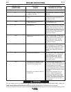
a. Check continuity between sockets 5
and 1 of keypad connector when
purge key is closed. If not, then
replace keypad, otherwise replace
Display PC board. (See Procedure
for Replacing PC boards).
a. Check continuity between sockets 4
and 1 of keypad connector when Cold
Feed key is closed. If not, then
replace keypad, otherwise replace
Display PC board. (See Procedure
for Replacing PC boards).
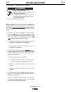
a. Ring out keypad. Replace if defec-
tive. If not, then replace Display PC
board. (See Procedure for Replacing
PC boards).


