


E-3
TROUBLESHOOTING
E-3
SYNERGIC 7 & 7H
Observe all Safety Guidelines detailed throughout this manual
If for any reason you do not understand the test procedures or are unable to perform the tests/repairs safely, contact your
Local Lincoln Authorized Field Service Facility for technical troubleshooting assistance before you proceed.
CAUTION
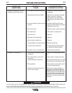
PROBLEMS
(SYMPTOMS)
POSSIBLE
CAUSE
RECOMMENDED
COURSE OF ACTION
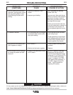
3. Poor arc striking with sticking or
“blast-offs”, weld porosity, narrow
and ropy looking bead, or elec-
trode stubbing into plate while
welding.
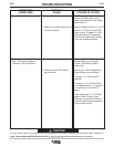
4. Tip seizes in diffuser.
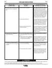
5. Unit shuts off while welding and
“HXX” appears on display.
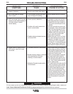
6. Drive roll does not turn although
arc voltage is present and sole-
noid is on.
a. Improper procedures or tech-
niques.
b. Improper gas shielding.
a. Tip overheating due to prolonged
or excessive high current and/or
duty cycle welding.
a. See Problem 1.
b.
Defective wire feed motor or gearbox.
a. Defective wire feed motor or con-
trol PC board.
a. See “Gas Metal Arc Welding
Guide” (GS-100).
b. Clean gas nozzle. Make certain that gas
diffuser is not restricted. Make certain that
gas cylinder is not empty or turned off.
Make certain gas solenoid valve is operat-
ing and gas flow rate is proper.
Remove gun liner and check rubber seal
for any sign of deterioration or damage. Be
sure set screw in brass connector is in
place and tightened against the liner bush-
ing.
a. Do not exceed current and duty
cycle rating of gun.
A light application of high temper-
ature antiseize lubricant (such as
Lincoln E2607 Graphite Grease)
may be applied to tip threads.
a. Correct problems causing motor
overload.
b. Replace.
a. Set Run-in speed to maximum.
Disconnect wire drive plug P5
from PC board. Measure voltage
across pin 1 (+) of J5 and pin 2 (-)
of J5 on PC board with trigger
closed. If voltage is ≥24 VDC,
then replace motor assembly. If
≤24 VDC, replace Control PC
board (see Procedure for
replacing PC boards).