


A-9
INSTALLATION
SYNERGIC 7 & 7H
A-9
ELECTRICAL INSTALLATION
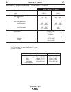
Input Cable: Synergic 7 Wire Feeder to Power
Wave Synergic Type Power Sources
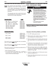
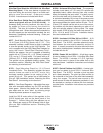
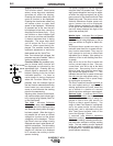
NOTE: CSAnrtl certification of the Synergic 7 models is with
input cable assemblies identified by carton date codes
010161, or above. These assemblies have grounding lead
continuity between the 14-pin plug pin B and the 8-socket
plug pin E per diagram below.
K649 - (Used with Power Wave 450/500) Consists of an 8-con-
ductor control cable with a 14-pin control cable plug and a 4/0
(107mm
2
) electrode cable with Twist-Mate™ connector. It is
rated at 500 amps, 60% duty cycle and is available in lengths of
7 ft (2 m), 17 ft (5 m), 25 ft (7.6 m), 33 ft (10 m) and 50 ft (15 m).
K675 - (Used with Power Wave 450/500) Similar to K649
but includes a gas hose with a 5/8-18 male fitting for the
Synergic 7 inlet. It is rated at 500 amps, 60% duty cycle
and is available in lengths of 7 ft. ( 2 m), 25 ft. (7.6 m) and
50 ft. (15 m).
K641- (Used with Power Wave 450/500 and Synergic 7/7H
with water quick connection) Similar to K649 but includes a
gas hose with a 5/8-18 male fitting for the Synergic 7 inlet
and water hoses with quick-connect male fittings to connect
between the water cooler and the Synergic 7 water connec-
tions. It is rated at 500 amps, 60% duty cycle and is avail-
able in lengths of 7 ft. (2 m), 17 ft. (5 m), 25 ft. (7.6 m), 33 ft.
(10 m) and 50 ft. (15 m).
K648 - (Used with Power Wave 450) Consists of an 8-con-
ductor control cable with a 14-pin plug and a 4/0 (107 mm
2
)
electrode cable with stud terminal. It is rated at 500 amps,
60% duty cycle and is available in lengths of 7 ft (2 m), 17 ft
(5 m), 25 ft (7.6 m), 33 ft (10 m) and 50 ft (15 m).
K676 - (Used with Power Wave 450) Similar to K648 but
includes a gas hose with a 5/8-18 male fitting for the
Synergic 7 inlet. It is rated at 500 amps, 60% duty cycle
and is available in lengths of 7 ft. (2 m), 25 ft. (7.6 m) and 50
ft. (15 m).
K640 - (Used with Power Wave 450 and Synergic 7/7H with
water quick-connection) Similar to K648 but includes a gas
hose with a 5/8-18 male fitting for the Synergic 7 inlet and
water hoses with quick-connect male fittings to connect
between the water cooler and Synergic 7 water connections.
It is rated at 500 amps, 60% duty cycle and is available in
lengths of 7 ft. (2 m), 25 ft. (7.6 m) and 50 ft. (15 m).
K651 - (Used with Power Wave 350) Consists of an 8-con-
ductor control cable with a 14-pin plug and 2/0 (67 mm2)
electrode cable with Twist-Mate™ connector. It is rated at
350 amps, 60% duty cycle and is available in lengths of 7 ft.
(2 m), 17 ft. (5 m), 33 ft. (10 m), and 50 ft. (15 m).
K677-7 - (Used with Power Wave 350) Similar to K651 but
includes a gas hose with a 5/8-18 male fitting for the
Synergic 7 inlet. It is rated at 350 amps, 60% duty cycle
and is available in 7 ft. (2 m) length.
K650 - (Used with Power Wave 350 and Synergic 7/7H with
water quick connection) Similar to K651 but includes a gas
hose with a 5/8-18 male fitting for the Synergic 7 inlet and
water hoses with quick-connect male fittings to connect
between the water cooler and the Synergic 7 water connec-
tions. It is rated at 350 amps, 60% duty cycle and is avail-
able in lengths of 7 ft. (2 m), 17 ft. (5 m), 33 ft. (10 m) and
50 ft. (15 m).
K642 (Control Cable Only) - Consists of an 8 conductor
control cable with a 14-pin control cable plug, without
elec-
trode cable, and is available in lengths of 7 ft (2 m), 17 ft (5
m), 25 ft (7.6 m), 33 ft (10 m) and 50 ft (15 m).
K643 (Control Cable Extension) - Consists of an 8 con-
ductor control cable with 14-pin connectors on each end for
extending the control cable between the power source and
the control cables. Available in lengths of 17 ft (5 m), 25 ft
(8 m), 33 ft (10 m) and 50 ft (15 m).
With input power disconnected from the power
source, install the input cable per connection diagram
S21041 in the rear of this manual and follow exactly
the instructions on the diagram or perform the follow-
ing:
1) Connect the end of the control cable with the 14-
pin cable plug to the mating receptacle on the
power source.
2) Connect the electrode lead of that same cable end
to the power source output terminal of the desired
polarity.
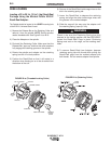
3) Route the other end of the electrode cable through
the large oval hole in the rear panel of the Synergic
7 case. Connect to the brass block on the side of
the gearbox using the bolt provided.
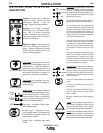
WARNING
Observe all additional Safety Guidelines detailed throughout this manual.
ELECTRIC SHOCK can kill.
• Do not touch electrically live parts such
as output terminals or internal wiring.
•
When inching with gun trigger, electrode and
drive mechanism are “hot” to work and
ground and could remain energized several
seconds after the gun trigger is released.
• Turn OFF input power at welding power
source before installation or changing
drive roll and/or guide tubes.
• Welding power source must be connected
to system ground per the National
Electrical Code or any applicable local
codes.
• Only qualified personnel should
perform this installation.
E=GND
8-PIN PLUG, FRONT VIEW
14-PIN PLUG, FRONT VIEW
B=GND