


V300-I
INSTALLATION
A-5 A-5
Return to Section TOC Return to Section TOC Return to Section TOC Return to Section TOC
Return to Master TOC Return to Master TOC Return to Master TOC Return to Master TOC
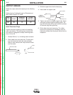
LN-9 GMA Connection Instructions (Not applicable
to machines with only 42V Aux.)
1. Turn the Invertec power switch “off”.
2. Connect the K596 or K1820-10 control cable
assembly from the LN-9 GMA to the Invertec control
cable connector. The control cable connector is
located at the rear of the Invertec.
3. Connect the electrode cable to the output terminal
of polarity required by electrode. Connect the work
lead to the other terminal.
4. Place the local-remote switch in the “remote” posi-
tion to allow output control at the LN-9 GMA.
5. Set the meter polarity switch on the rear of the
Invertec to coincide with wire feeder polarity used.
The wire feeder will now display the welding volt-
age.
6. K608-1* adapter is required in LN-9 GMA for LN-9
type control. K608-1 is installed in line with P10. See
diagram S20607.
7. K442-1* Pulse Power Filter Board is also required
for GMAW,but should beremoved for FCAW.
8. If K596 is not available, see connection diagram
S20608 for modification of K196 LN-9 GMA input
cable with K867 universal adapter plug.
* These kits are no longer available.
GENERAL INSTRUCTIONS FOR CONNEC-
TION OF WIRE FEEDERS TO INVERTEC
Wire feeders other than LN-7 and LN-25 may be used
provided that the auxiliary power supply capacity of the
Invertec is not exceeded. K867 universal adapter plug
is required. See connection diagram S19406 and
S19386 for more information.
Remote Control of Invertec
Remote control K857, hand amptrol K963 and foot
amptrol K870 require K864 remote control adapter.
See connection diagram S19309.
K954-1 MIG PULSER
The MIG Pulser is a hand-held “pendant” type GMAW
Pulsing option for the V300-I Power Source. See the
Mig Pulser’s IM manual (IM555) for connection
information.
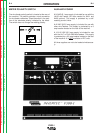
K900-1 DC TIG STARTER CONNECTION
This versatile new kit was made to mate with the
Invertec
A control cable assembly is supplied with the kit to
connect the kit to an Invertec. The cable can be con-
nected, either end, at the DC TIG Starter kit and at
the Invertec by attaching to the 14-pin Amphenols on
the backs of each unit. See diagram S20405.
A negative output cable assembly is also supplied
with the DC TIG Starter kit to connect the kit with the
Invertec’s negative output terminal.
All Magnum™ one and two piece water-cooled
torches with 7/8 left-hand threads and gas-cooled
torches with 7/8 and 5/16 right-hand threads can be
connected to the starter kit.
To secure the DC TIG Starter kit to the bottom of the
Invertec and for more detailed instructions, see the
K900-1 (IM465) manual.
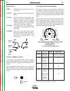
PARALLEL OPERATION
The Invertec is operable in parallel in both CC and
CV modes. For best results, the currents of each
machine should be reasonably well shared. As an
example, with two machines set up in parallel for a
400 amp procedure, each machine should be set to
deliver approximately 200 amps, not 300 amps from
one and 100 amps from the other. This will minimize
nuisance shutdown conditions. In general, more than
two machines in parallel will not be effective due to
the voltage requirements of procedures in that power
range.
To set machine outputs, start with output control pots
and arc force/pinch pots in identical positions. If run-
ning in a CC mode, adjust output and arc force to
maintain current sharing while establishing the prop-
er output current. In CV modes, the pots in identical
positions. Then switch the machine meters to amps
and adjust one of the output control pots for current
balance. Check the voltage and if readjustment is
necessary, repeat the current balancing step. Pinch
settings should also be kept identical on the
machines.