


V300-I
TROUBLESHOOTING & REPAIR
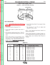
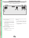
6. Turn main power OFF.
7. Perform Input Filter Capacitor Discharge
Procedure detailed in this section.
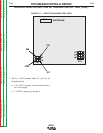
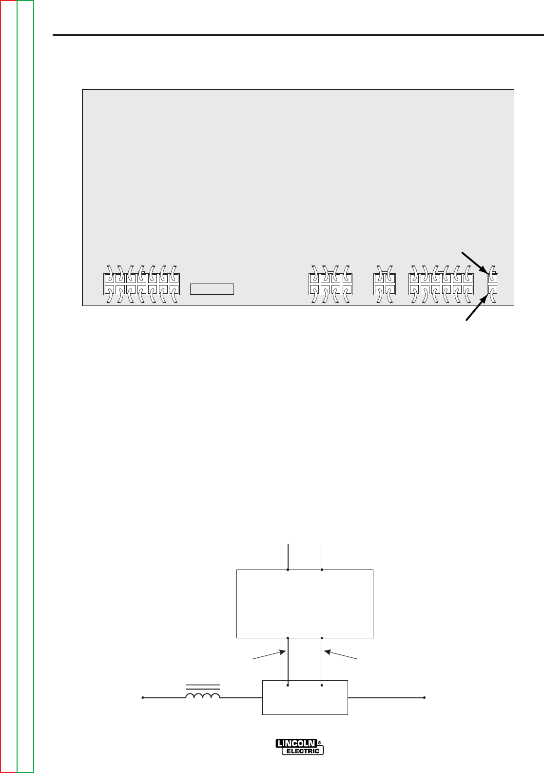
Test resistance of the Black and White leads from
1J3 and 2J3 to the shunt. See Figure F.14.
a. If zero ohms resistance (continuity) is shown,
test is OK.
b. If resistance of any value is shown, check wire
and connections.
NOTE: On earlier codes the terminals on the shunt
leads were crimped but not soldered. Corrosion may
cause inaccurate current readings. Cleaning and sol-
dering the terminals to the leads may eliminate that
problem.
If tests for steps 5, 7, are OK and the machine contin-
ues to experience the problem, the Control Board
should be replaced.
F-37 F-37
Return to Section TOC Return to Section TOC Return to Section TOC Return to Section TOC
Return to Master TOC Return to Master TOC Return to Master TOC Return to Master TOC
OVERCURRENT PROTECTION CURRENT TRIGGER TEST (cont.)
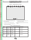
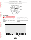
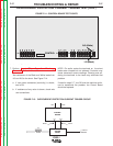
FIGURE F.14 - CONTROL BOARD TEST POINTS
G2527
CONTROL
1J3 (Black)
2J3 (White)
J5 J1
J2
J4
J3
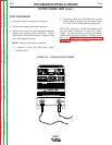
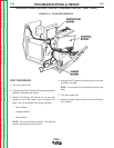
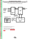
FIGURE F.15 - OVERCURRENT PROTECTION CURRENT TRIGGER CIRCUIT.
BLACK
CHOKE
WHITE
(-) OUTPUT
TERMINAL
6J1
302 275D
1J3
L3
1J1
2J3
CONTROL
BOARD
400 AMP
SHUNT