


V300-I
TROUBLESHOOTING & REPAIR
F-18 F-18
Return to Section TOC Return to Section TOC Return to Section TOC Return to Section TOC
Return to Master TOC Return to Master TOC Return to Master TOC Return to Master TOC
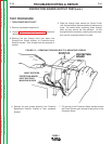
TEST PROCEDURE
1. TURN POWER SWITCH OFF
2. Remove sheetmetal wraparound.
3.
Perform Input Filter Capacitor Discharge procedure
detailed in Maintenance section
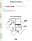
4. Remove the two through bolts that attach the
Power/Driver Board bracket to Protection/Input
Rectifier bracket. Each through bolt also supports a
resistor
.
5. Slide the through bolts toward the Control Panel
until the brackets are disconnected and resistors are
loose. Be careful when loosening these through
bolts, as they secure the two resistors. As the
through bolts are removed, carefully place the resis-
tors and the connected wires to the side
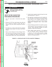
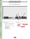
PROTECTION BOARD OUTPUT TEST(cont.)
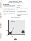
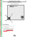
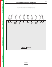
FIGURE F.4 — REMOVING THROUGH BOLTS & MOUNTING SCREWS
INPUT RECTIFIER
PROTECTION BOARD/
INPUT RECTIFIER
MOUNTING SCREW
6. Remove the two screws attaching the Protection
Board/Input Rectifier bracket to main assembly
bracket.
7. Tilt the top of the Protection Board bracket toward
the Power Panel to gain access to test points on the
Protection Board.