


V300-I
INSTALLATION
A-3 A-3
Return to Section TOC Return to Section TOC Return to Section TOC Return to Section TOC
Return to Master TOC Return to Master TOC Return to Master TOC Return to Master TOC
THE LINCOLN ELECTRIC CO. CLEVELAND, OHIO U.S.A.
.
.
.
.
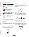
Do not touch electrically live parts.
Only qualified persons should install,
use or service this equipment.
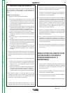
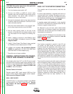
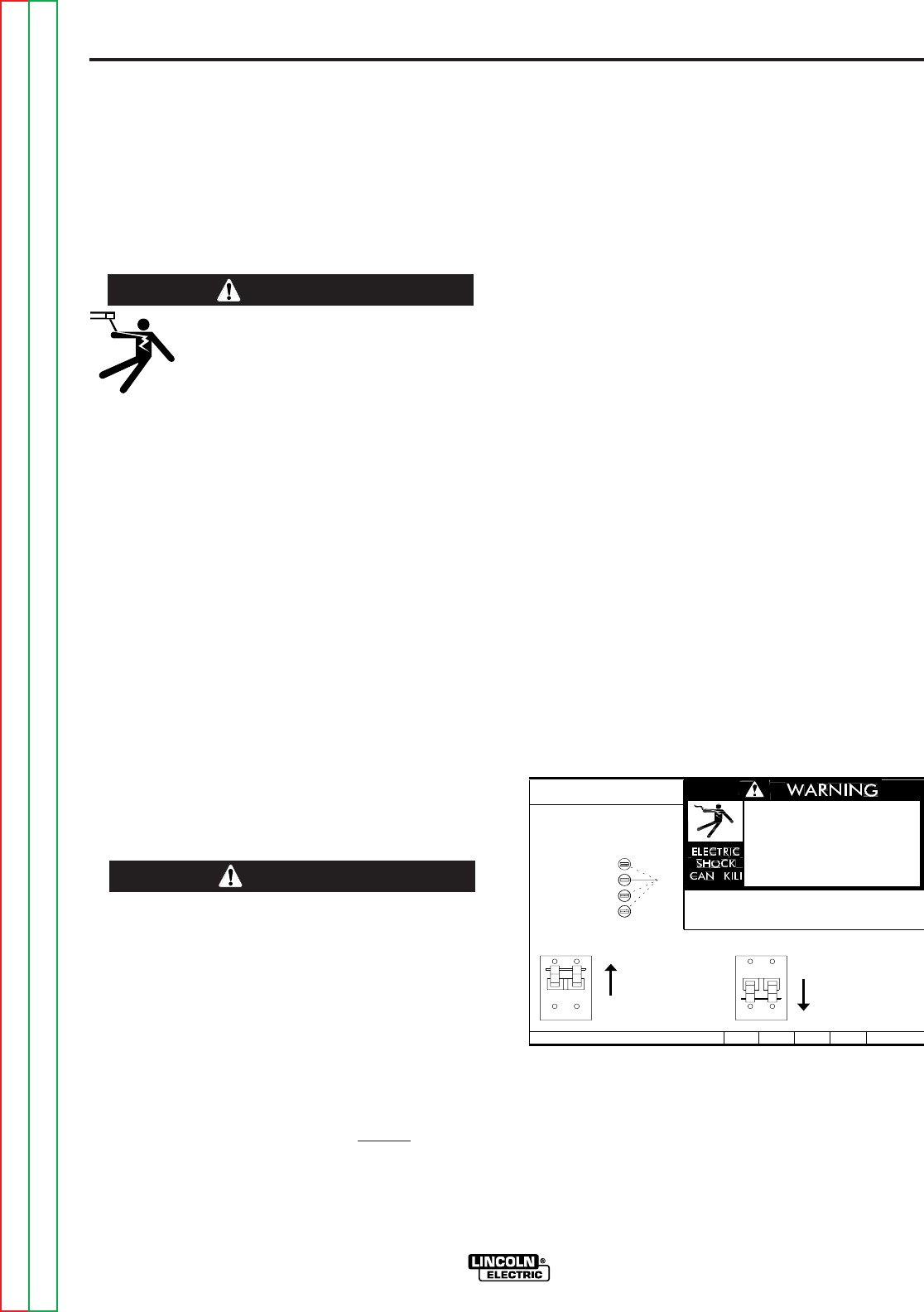
RECONNECT PROCEDURE
REPLACE WITH A 3 AMP SLOW BLOW ONLY.
1. BE SURE POWER SWITCH IS OFF.
200-208V
220-230V
380-415V
440-460V
’A’
INPUT VOLTAGE RANGE.
removed.
Do not operate with wraparound
inspecting or servicing machine.
Disconnect input power before
IF MACHINE CEASES TO OPERATE (NO METER, NO FAN)
2. CONNECT LEAD ’A’ TO DESIRED
3. POSITION SWITCH TO DESIRED INPUT VOLTAGE RANGE.
S20324
AND THERE IS NO OTHER KNOWN FAILURE: CHECK FUSE;
VOLTAGE=380-460V
VOLTAGE=200-230V
9-11-92
DO NOT ATTEMPT TO POWER THIS UNIT
FROM THE AUXILIARY POWER SUPPLY
OF AN ENGINE WELDER.
• Special protection circuits may operate, causing
loss of output.
• The supply from engine welders often has exces-
sive voltage peaks because the voltage waveform is
usually triangular shaped instead of sinusoidal.
• If voltage peaks from the engine welder are too high
(380v on 230v setting), the input circuits of this
machine protecting the filter capacitors, FETS and
other components from damage will not
be ener-
gized.
CAUTION
PRODUCT DESCRIPTION
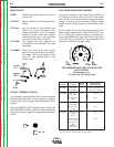
The Invertec V300-I is a 300 amp arc welding power
source that utilizes single or three phase input power to
produce either constant voltage or constant current
outputs. The V300-I is designed for 50/60 Hz supply
systems. The welding response of the Invertec has
been optimized for GMAW, SMAW, TIG and FCAW
processes. It is designed to be used with the LN-25
and LN-7 semiautomatic wire feeders.
ELECTRIC SHOCK can kill.
• Have an electrician install and ser-
vice this equipment.
• Turn the input power off at the fuse
box before working on equipment.
• Do not touch electrically hot parts.
----------------------------------------------------------------------
WARNING
LOCATION
The Invertec has been designed with many features to
protect it from harsh environments. Even so, it is
important that simple preventative measures are fol-
lowed in order to assure long life and reliable opera-
tion.
• The machine must be located where there is free cir-
culation of clean air such that air movement into the
sides and out the bottom and front will not be
restricted. Dirt and dust that can be drawn into the
machine should be kept to a minimum. Failure to
observe these precautions can result in excessive
operating temperatures and nuisance shutdown of
the Invertec.
• Keep machine dry. Shelter from rain and snow. Do
not place on wet ground or in puddles.
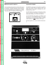
ELECTRICAL INSTALLATION
1. The Invertec should be connected only by a quali-
fied electrician. Installation should be made in
accordance with the U.S. National Electrical Code,
all local codes and the information detailed below.
2. When received from the factory, multiple voltage
(200/220/380-415/440) machines are internally
connected for 440 volt input.
3. Single voltage, 575 VAC machines, can only be
connected to 575 VAC. No internal reconnection
for other input voltages is possible.
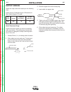
4. Initial 208 VAC and 230 VAC operation will require
a voltage panel setup, as will later reconnection
back to 460 VAC:
a. Open the access panel on the right side of
the machine.
b. For 208 or 230: Position the large switch to
200-230.
For 460: Position the large switch to 380-460.
c. Move the “A” lead to the appropriate terminal.
CAUTION: DO NOT CHANGE SWITCH
POSITION WITH INPUT POWER
APPLIED. MAJOR DAMAGE WILL
RESULT.
INPUT VOLTAGE SETUP