


V300-I
F-15 F-15
Return to Section TOC Return to Section TOC Return to Section TOC Return to Section TOC
Return to Master TOC Return to Master TOC Return to Master TOC Return to Master TOC
TROUBLESHOOTING & REPAIR
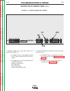
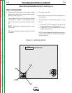
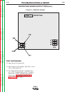
FIGURE F.3 – CONTROL BOARD TEST POINTS
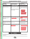
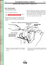
OUTPUT PILOT CIRCUIT TEST (cont.)
7. Measure voltage from Lead #210 (J2/Pin 4) to
Lead # 223A (J4/Pin 11).
a. If voltage is 24v.a.c., thermostats, transfor
mer T1 and switch (S4) are OK. Go on to
Step 8.
b. If voltage is 0v.a.c. test the following com
ponents individually:
Auxiliary Transformer T1
Fan Thermostat
Choke Thermostat
Output Terminal Switch (S4)
8. Measure voltage from lead 302 (J1/Pin 6) to Lead
275D (J1 /Pin1).
a. If voltage is 15v.d.c, Transformer T1 and 15
volt supply are OK. Go to Protection Board
Output test.
b.If voltage is 0v.d.c. check Transformer T1
and then go to Power Board test
G2527
CONTROL
210
302
275D
223A
J5
J1
J2
J4
J3