


V300-I
F-14 F-14
Return to Section TOC Return to Section TOC Return to Section TOC Return to Section TOC
Return to Master TOC Return to Master TOC Return to Master TOC Return to Master TOC
TROUBLESHOOTING & REPAIR
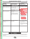
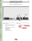
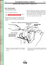
TEST PROCEDURE
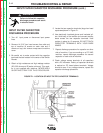
1. Turn Input Power Switch OFF
2. Perform Input Capacitor Discharge test as
described in the Maintenance Section.
3. Remove the four screws that hold the Control Panel
to the frame.
4. Move the Control Panel forward and to the left so
that there is access to the Control PC Board. Be
careful not to stress any of the connections to the
Control Panel.
5. Set the Output Terminals Switch to the ON position.
6. Turn the Input Power Switch ON.
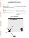
FIGURE F.2 - REMOVING CONTROL PANEL
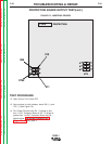
OUTPUT PILOT CIRCUIT TEST(cont.)