


V300-I
TROUBLESHOOTING & REPAIR
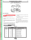
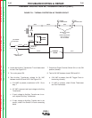
8. Test for 15 VDC supply voltage between leads 302
and 275D on Power Board.
a. If 15 VDC is present, test is OK. Go to step 9.
b. If 15 VDC is not present, the Power Board may
be faulty. Check for 18 VAC input voltage at
lead 501 and 504 (J7).
If 18 VAC is present the Power Board is faulty
and must be replaced.
9. Test for 0-1 VDC (DC trigger circuit) between leads
305 and 275D on Power Board.
a. If 0-1 VDC is present, DC trigger circuit is oper-
ating properly.
b. If 15 VDC is present, go to step 10.
10. Test for 0-1 VDC between leads 301 and 275D on
Power Board.
a. If 0-1 VDC is present, AC trigger, Control
Board, and Power Board are operating proper-
ly.
b. If 15 VDC is present, go to Thermal Protection
AC Trigger Circuit Test .
F-41 F-41
Return to Section TOC Return to Section TOC Return to Section TOC Return to Section TOC
Return to Master TOC Return to Master TOC Return to Master TOC Return to Master TOC
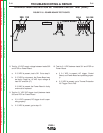
OVERVOLTAGE PROTECTION DC TRIGGER CIRCUIT TEST (cont.)
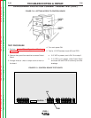
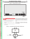
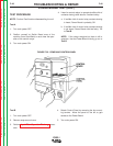
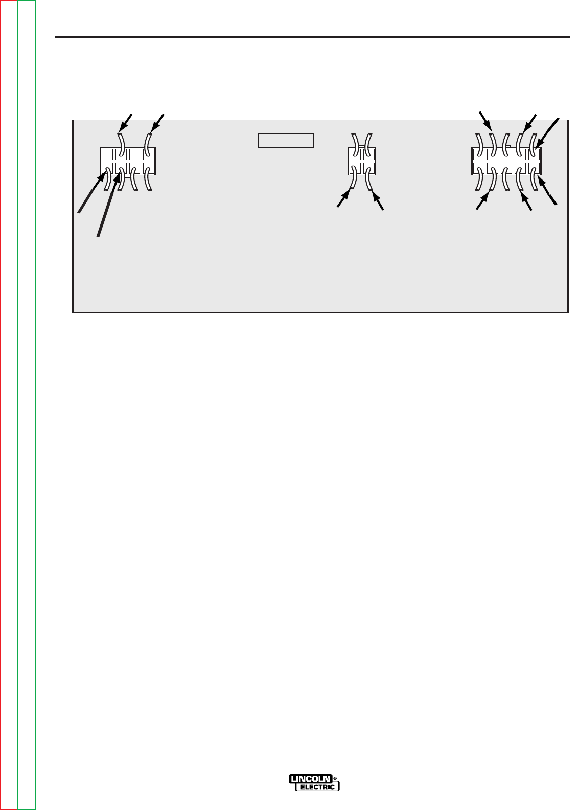
FIGURE F.18 - POWER BOARD TEST POINTS
POWER BOARD
J6
J7
J14
L8033
501
313
311
309 310
504
302
305
301
212A
211A
275D