


V300-I
TROUBLESHOOTING & REPAIR
F-19 F-19
Return to Section TOC Return to Section TOC Return to Section TOC Return to Section TOC
Return to Master TOC Return to Master TOC Return to Master TOC Return to Master TOC
PROTECTION BOARD OUTPUT TEST(cont.)
TEST PROCEDURE
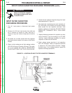
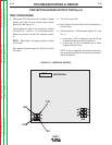
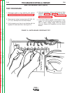
8. With power OFF, disconnect J8 and attach voltage
probes into back of wire harness lead junction
block (J8). See Figure F.5.
Insert probes into back of the connection cavities
for leads 313 (-) and 311 (+) of Protection Board.
Make sure contact is made with conductor materi-
al.
NOTE: Right-angle, thin-gauge probes are best
for this test.
With probes attached, plug the (J8) block into the
PC board.
9. Turn main power ON.
10. Move Output Terminal Switch S4 to ON position on
Control Panel.
11. Test for less than 1 VDC between leads 313 (-) and
311 (+).
a. If less than 1 VDC is measured, test is OK and
Protection Board is functioning properly.
b. If more than 5 VDC is measured, go to Static
Capacitor Balance Test.
NOTE: During voltage test, be cautious when posi-
tioning loose components to avoid shorts and dam-
age to equipment.
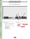
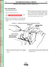
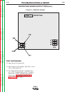
FIGURE F.5 - INSERTING PROBES
PROTECTION
L7915
306
313
275F
311
J8
J15