


V300-I
TROUBLESHOOTING & REPAIR
PROCEDURE (Paralleled IndividualDiodes)
1. Turn main power OFF.
2. Perform Input Filter Capacitor Discharge proce-
dure detailed in Maintenance section..
3. Detach and remove both Switch Board assemblies
and attached capacitors. See Switch Board
Removal and Replacement procedure
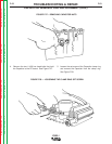
4. Detach the fan shroud to gain access to the diode
heat sink and mounting bracket. When the fan
shroud is lifted, the tabs securing the heat sink
mounting bracket will release.
5. Move the diode heat sink and mounting bracket
away from the Case Back.
6. Un-solder the leads from each of the diodes to be
replaced.
7. Remove the nut that secures each diode to the heat
sink and mounting bracket.
8. Mount the replacement diodes to the heat sink.
IMPORTANT: The replacement diodes will come
with an instruction sheet that addresses surface
preparation and torque values. Failure to follow
these instructions may result in subsequent break
down.
9. Carefully resolder the leads to the new diodes.
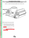
10. Reassemble the unit being careful to use all of the
insulating materials. Also make certain to replace
all disconnected leads in their proper location.
Failure to do so may result in machine damage
when the power is applied.
11. Perform the Test After Switch Board or
Capacitor Replacement .
F-60 F-60
Return to Section TOC Return to Section TOC Return to Section TOC Return to Section TOC
Return to Master TOC Return to Master TOC Return to Master TOC Return to Master TOC
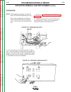
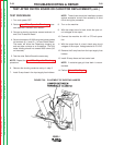
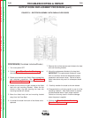
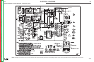
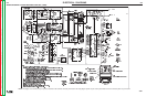
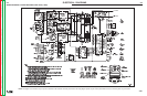
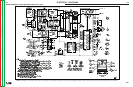
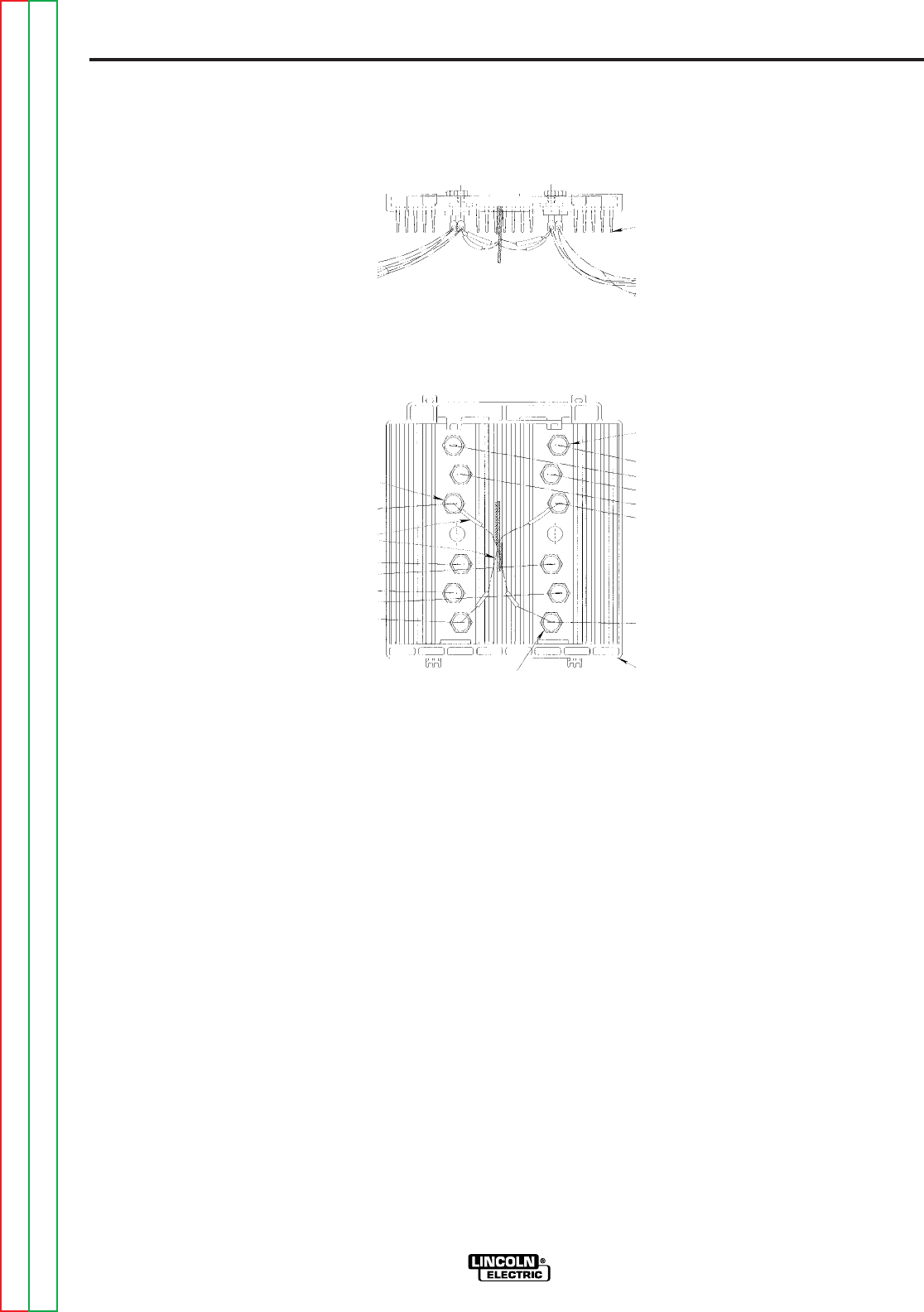
OUTPUT DIODE REPLACEMENT PROCEDURE (cont.)
FIGURE F.31 - RECTIFIER ASSEMBLY WITH PARALLELED DIODES