


V300-I
TROUBLESHOOTING & REPAIR
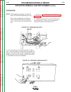
PROCEDURE
NOTE: When replacing capacitors, remove the
entire FET Heat Sink Assembly as a unit.
Remove and reassemble one side at a
time, using the other side as a model to
insure that all parts are reinstalled prop
erly
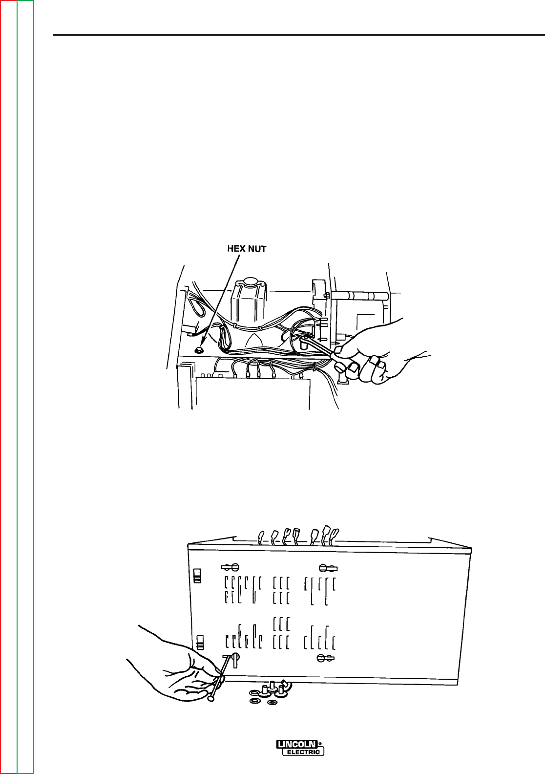
1. Perform the Input Filter Capacitor Discharge
Procedure.
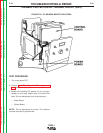
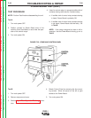
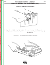
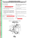
2. Remove the two 3/8” hex nuts from the top of
the through bolts. The hex nuts are located on
top of the fan shroud See Figure F.25.
F-52 F-52
Return to Section TOC Return to Section TOC Return to Section TOC Return to Section TOC
Return to Master TOC Return to Master TOC Return to Master TOC Return to Master TOC
CAPACITOR REMOVAL AND REPLACEMENT (cont.)
FIGURE F.25 - REMOVING HEX NUTS
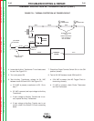
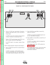
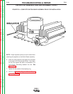
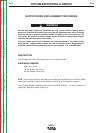
3. Turn the machine on it’s side as shown in Figure
F.26. Slide the plastic insulators that go through the
base to one side and pull out the through bolts, being
careful to save all of the insulation and standoff materi-
al. Set aside and save for reassembly.
FIGURE F26 - REMOVING THROUGH BOLTS