


OPERATION
B-9 B-9
INVERTEC® V205-T AC/DC™
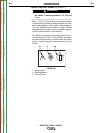
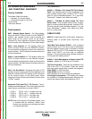
AC TIG - NOT PULSED
Ip
Im
Ib
O
O
t
t
T
f = 1 to 10Hz
T= 1/ f
I
AC - PULSED TIG
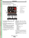
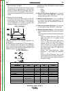
DC Electrode Positive Polarity. (Direct Current
Reverse Polarity) (see Figure B.5)
In this case, there is a continuous flow of electrons
from the workpiece to the electrode. The reverse polar-
ity is used for welding alloys covered with a layer of
refractory oxide.
With this polarity the electrode functions as anode and
is subjected to a high degree of heat; the workpiece is
bombardment by positive ions sent from the electrode
which break the surface oxide.
In Electrode Positive Polarity, high currents cannot be
used, since they would cause an excessive wear of the
electrode.
NOTE: (The Invertec® V205-T AC/DC™ cannot be
used for Electrode Positive TIG welding without
special adapters.)
FIGURE B.5
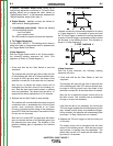
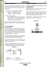
D.C.-Pulsed TIG
(see Figure B-6)
The use of pulsed direct current allows better control of
the weld pool during certain operating conditions.
When compared with traditional TIG welding per-
formed at the same average current, pulsed welding
results in a smaller heat affected zone which results in
fewer deformations and reduced chance of cracking
and gas entrapment.
Increasing the frequency constricts the arc, increases
stability and improves weld quality.
FIGURE B.6
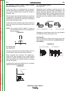
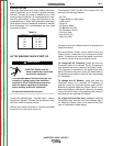
A.C. (Alternating Current)
(see Figure B.7)
Alternating Current welding is typically used for Tig
welding aluminum (and its alloys) or magnesium. The
polarity alternates between Electrode Positive and
Electrode Negative (EN). During the positive half-wave
the oxide is broken. During the negative half-wave, the
electrode cools, the workpiece melts and penetration
occurs.
FIGURE B.7
Changing the wave balance alters the ratio between
the cleaning and the penetrating current.
1
e-
+
–
T
Is
O
t
T
Is
O
t
m
Ib
T
DC TIG - NOT PULSED
DC - PULSED TIG
+
+
+
---
30% MAX. PENETRATION
50%
70% MAX. CLEANING
Greater % EN = MORE PENETRATION
50% (EN)
Lesser % EN = more CLEANING
A.C.-Pulsed TIG
When AC welding, a pulsed current can be used, with
similar effects to those described in pulsed direct cur-
rent welding.
FIGURE B.8
Return to Section TOC Return to Section TOC Return to Section TOC Return to Section TOC
Return to Master TOC Return to Master TOC Return to Master TOC Return to Master TOC