


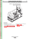
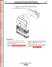

BACK SIDE
MAIN BOARD
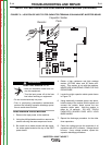
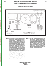
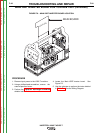
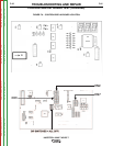
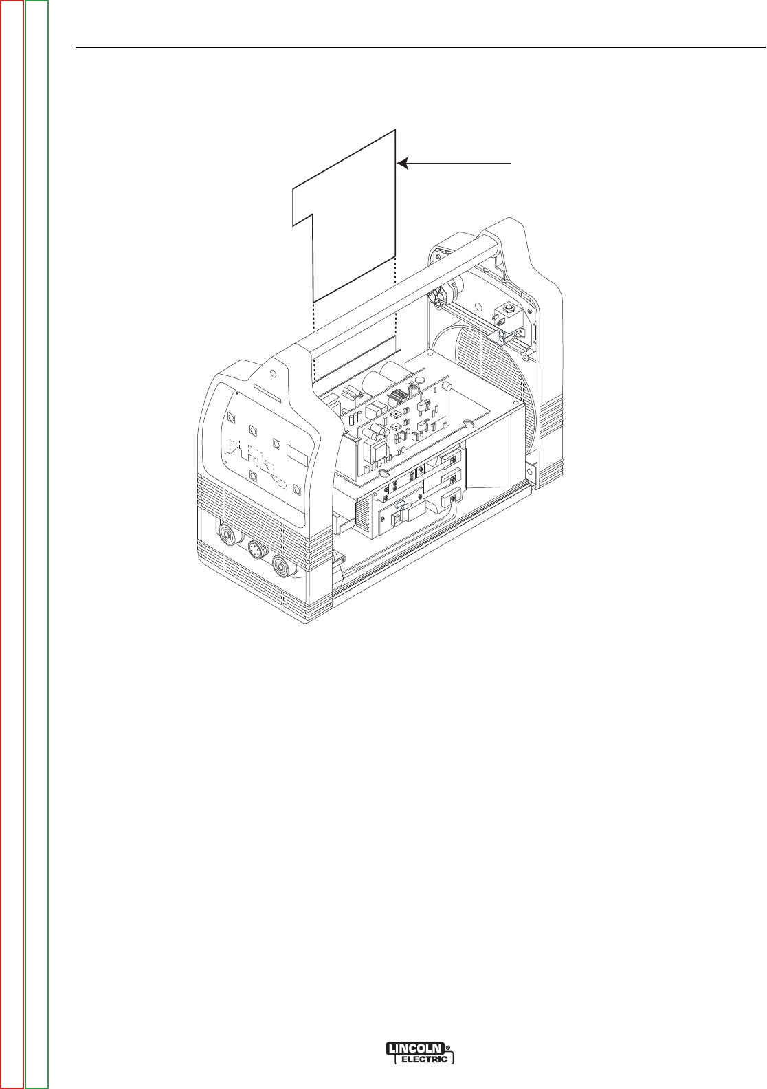
FIGURE F.6 – MAIN IGBT INVERTER BOARD LOCATION
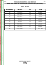
MAIN IGBT INVERTER BOARD LOW VOLTAGE TEST (continued)
PROCEDURE
1. Remove input power to the V205-T machine.
2. Using a phillips head screwdriver, remove the
case wraparound cover.
3. Perform the Capacitor Discharge Procedure
detailed earlier in this section.
4. Locate the Main IGBT Inverter board. See
Figure F.6.
5. Use the voltmeter to perform the tests detailed
in Table F.1. See the Wiring Diagram.
TROUBLESHOOTING AND REPAIR
F-20 F-20
INVERTEC® V205-T AC/DC™
Return to Section TOC Return to Section TOC Return to Section TOC Return to Section TOC
Return to Master TOC Return to Master TOC Return to Master TOC Return to Master TOC