


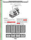
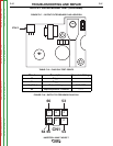
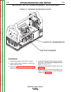
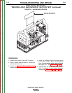
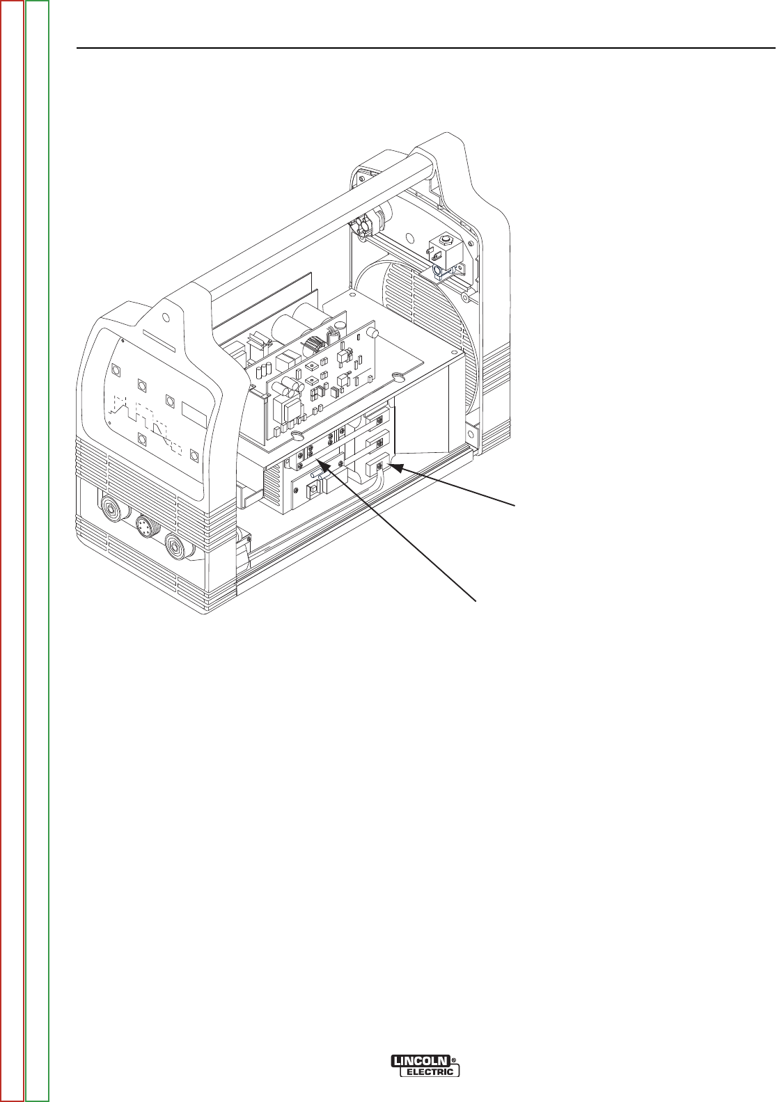
OUTPUT TRANSISTOR
OUTPUT DIODES
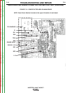
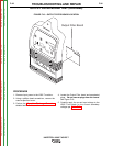
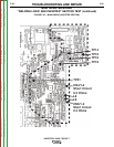
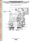
FIGURE F.19 – SECONDARY POWER BOARD LOCATION
SECONDARY OUTPUT BOARD ASSEMBLY TEST (continued)
PROCEDURE
1. Remove input power to the V205-T machine.
2. Using a phillips head screwdriver, remove the
case wraparound cover.
3. Perform the Capacitor Discharge Procedure
detailed earlier in this section.
4. Locate the Secondary Power board and associ-
ated plugs. Do not remove plugs from the
board. See Figure F.19.
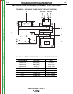
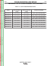
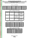
5. Perform the output diode resistance check per
Table F.13.
6. Carefully apply the correct input voltage to the
V205-T and check for the correct secondary
voltages per Table F.13.
TROUBLESHOOTING AND REPAIR
F-40 F-40
INVERTEC® V205-T AC/DC™
Return to Section TOC Return to Section TOC Return to Section TOC Return to Section TOC
Return to Master TOC Return to Master TOC Return to Master TOC Return to Master TOC